

Church-turing thesis: the turing immortality problem solved with a dynamic register machine
a register machine and immortality technology, applied in the field of church-turing thesis, can solve the problems that the the current computing machine implementation and software applications have been unable to solve this problem and other computing problems, and the turing immortality problem cannot be solved by turing machines
- Summary
- Abstract
- Description
- Claims
- Application Information
AI Technical Summary
Benefits of technology
Problems solved by technology
Method used
Image

Examples
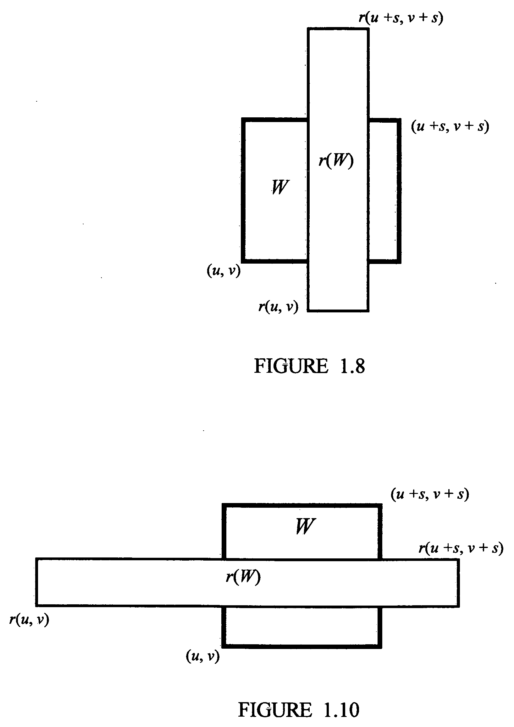
example 1.12
[0088]r(xy)=(1 / 2002)(xy)+(410110)
with Standard Unit Square U(0, 0).
[0089]The fixed point
(810,-110)
is not in U(0, 0). The geometry is shown in FIG. 1.12
Theorem 1.13
Vertical Covering Fixed Point Theorem
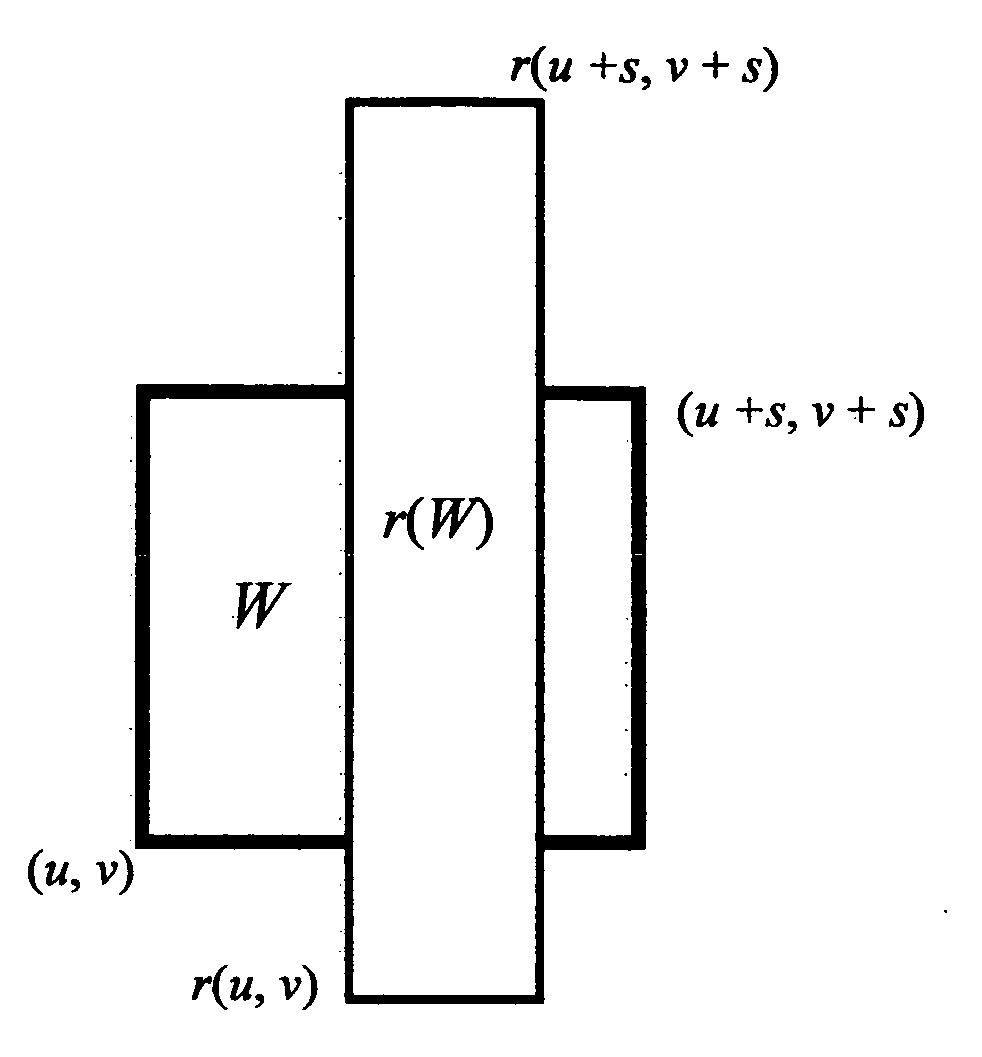
[0090]Consider the rectangular, area-preserving affine map
r(xy)=(1A00A)(xy)+(mn)
for some A>1 and square domain W=[(u, v), (u+s, v), (u+s, v+s) (u, v+s)]. Then r(W) vertically covers W if and only if fixed point
(mAA-1,n1-A)
lies in W.
Proof.
[0091]Define
r′(xy)=r(xy)-(uv)
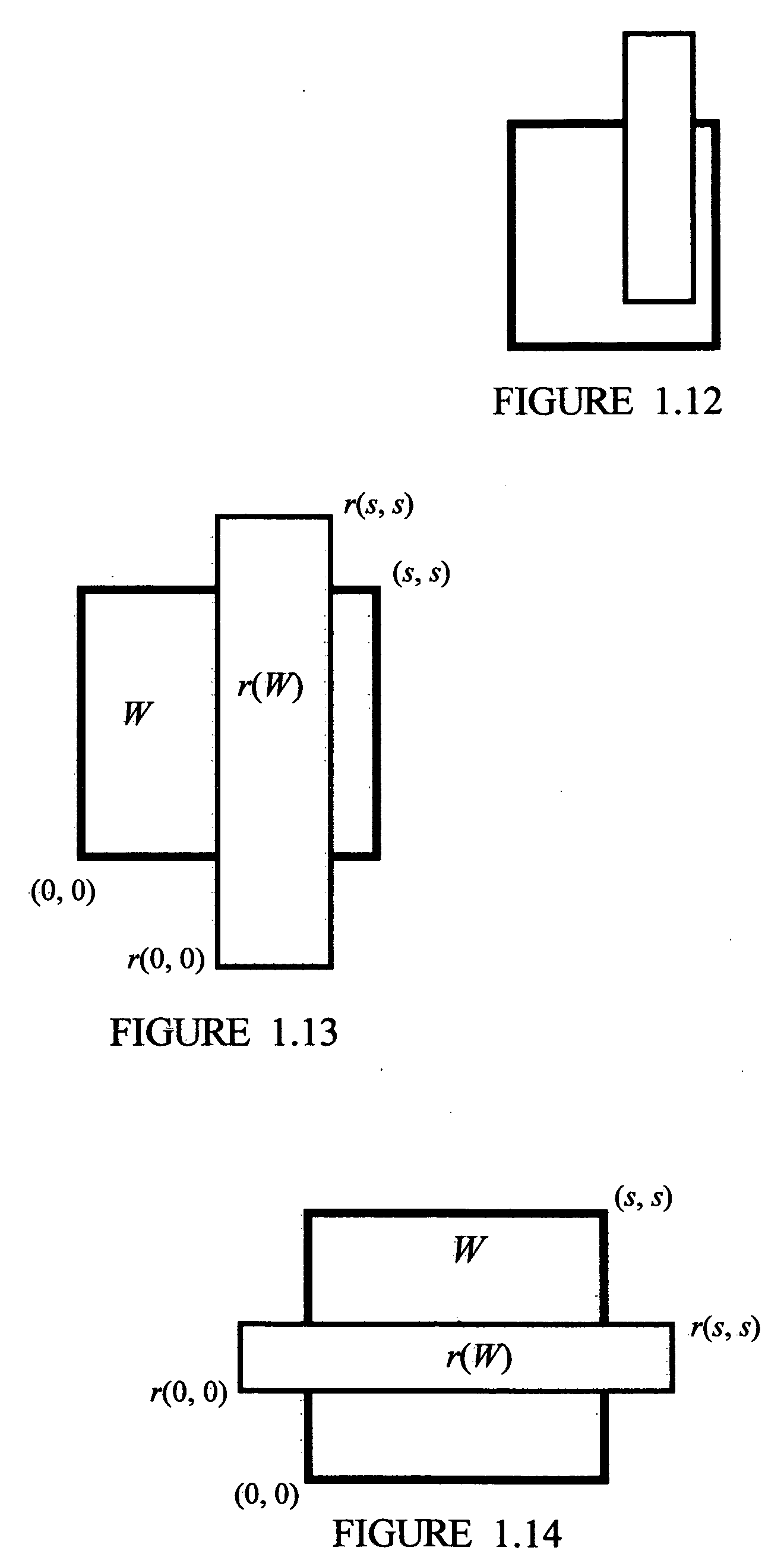
to translate W so that W is a square of sides with length s with lower left corner at the origin. Thus, without loss of generality, it suffices to verify it for domain W=[(0, 0), (s, 0), (s, s), (0, s)]. Observe that r(0, 0)=(m, n) and
r(s,s)=(m+sA,n+sA).
[0092]The geometry is shown in FIG. 1.13. Observe that
1.) The y-coordinate of r(0, 0)=n
2.) The y-coordinate of r(s, s)=n+sA
3.) The x-coordinate of r(0, 0)=m
4.) The x-coordinate of
r(s,s)=m+sA(⇔)(mAA-1,n1-A)
lies in W
iff0≤n1-A≤sAND0≤mAA-1≤siff[n≤0ANDn≥(1-A)s]AND[0≤mA≤(A-1)s]iff[...
example 1.16
[0101]f(xy)=(14004)(xy)+(40)
on domain U(0, 0) and
g(xy)=(14004)(xy)+(-10)
on U(4, 0)
[0102]g·f(xy)=(1160016)(xy)+(00)andf(00)=(40)f(10)=(4.250)f(01)=(41)
(0, 0) is a fixed point of g ƒ. The orbit of any point p chosen from the horizontal segment connected by the points (0, 0) and (1,0) with respect to the function sequence [ƒ, g, ƒ, g, . . . ] is a subset of U(0, 0)∪U(4, 0). The point p is called an immortal point. The orbit of a point Q outside this segment exits (halts) U(0, 0)∪U(4, 0).
Definition 1.17
Halting and Immortal Orbits in the Plane.
[0103]Let P denote the two dimensional x, y plane. Suppose ƒk: Uk→P is a function for each k such that whenever j≠k, then Uj∩Uk=Ø. For any point p in the plane P an orbit may be generated as follows. The 0th iterate of the orbit is p. Given the kth iterate of the orbit is point q, if point q does not lie in any Uk, then the orbit halts. Otherwise, q lies in at least one Uj. Inductively, the k+1 iterate of q is defined as ƒj(q). If p has an orbit th...
example 2.4
Turing Machine Configuration
[0123]Consider configuration (p, 2, . . . ##αβ## . . . ). The first coordinate indicates that the Turing machine is in state p. The second coordinate indicates that its tape head is currently scanning tape square 2, denoted as T2 or T(2). The third coordinate indicates that tape square 1 contains symbol α, tape square 2 contains symbol β, and all other tape squares contain the # symbol.
PUM
 Abstract
Description
Claims
Application Information