Wireless Tracking System And Method Utilizing Near-Field Communication Devices

a tracking system and communication device technology, applied in data switching networks, program control, instruments, etc., can solve problems such as insufficient resource visibility in a business and prior art failure to provide an adequate solution to these problems, and achieve the effect of increasing the transmission ra

Inactive Publication Date: 2011-03-24
AWAREPOINT CORPORATION
View PDF36 Cites 36 Cited by
  • Summary
  • Abstract
  • Description
  • Claims
  • Application Information

AI Technical Summary

Benefits of technology

[0034]Each communication device preferably has a low-power, short-range (<1 foot) communication feature that can detect the presence, or absence, of a signal from another device. Short bits of information are preferably exchanged (<256 bits) between devices but such an exchange is not mandatory. RFID systems operating at frequencies of sub-125 kHz, 125 kHz, 433 MHz, 900 MHz, or 2.4 GHz are used with the present invention. The communication devices alternatively transmit at frequencies as low as 5 kiloHertz (“kHz”) and as high as 900 MegaHertz (“MHz”). Other frequencies utilized by the tags for a low-power short-range communication system include 9 kHz, <125 kHz, 433 MHz, and 900 MHz.
[0035]Each device preferably contains a low-power, medium-range (1 foot to 30 feet) wireless communication system. Such wireless communication systems include ZIGBEE, BLUETOOTH, Low-Power BLUETOOTH, WiFi or Low-Power WiFi, Ultra Wide Band (“UWB”), Ultrasound and Infrared communication systems. The wireless communication system is used to exchange device specific information after the low-power short-range system has indicated that an interaction has occurred. Those skilled in the pertinent art will recognize that the wireless communication system can also be used independent of the low-power short-range system for other wireless communication applications such as location and tracking, sense and control, building automation, smart energy, telecom applications, consumer building automation, remote control applications, home health care, personal fitness, personal wellness, and many other applications.
[0036]Each communication device preferably continuously transmits a beacon signal using the short-range communication protocol. When a beacon signal is received by another communication device, the receiving communication device can respond using the low-power communication circuit and / or it can respond using the medium-power protocol. The medium-power communication system can transfer larger data packets at a higher transmission rate. Data that might be included in a medium-power transmission include device ID, time stamp, location information, user information, software version, and / or protocol version. A medium-power transmission is preferably acknowledged when received by the receiving communication device. Further, at this point either communication device, or both communication devices, can transmit the information from the interaction to the medium-power infrastructure or to a neighboring communication device. Additionally, the communication devices may also elect to store the interaction information and download / transmit the interaction information at a later time.

Problems solved by technology

As stated above, the problem is inadequate resource visibility in a business.
Specific problems for hospitals include tracking infections in a hospital to determine a source and other areas or individuals that may be infected.
Other problems include spotting emerging patterns of infection and outbreaks to mitigate those affected.
The prior art has failed to provide an adequate solution to these problems.

Method used


Image

  • Wireless Tracking System And Method Utilizing Near-Field Communication Devices
  • Wireless Tracking System And Method Utilizing Near-Field Communication Devices
  • Wireless Tracking System And Method Utilizing Near-Field Communication Devices

Examples


Embodiment Construction

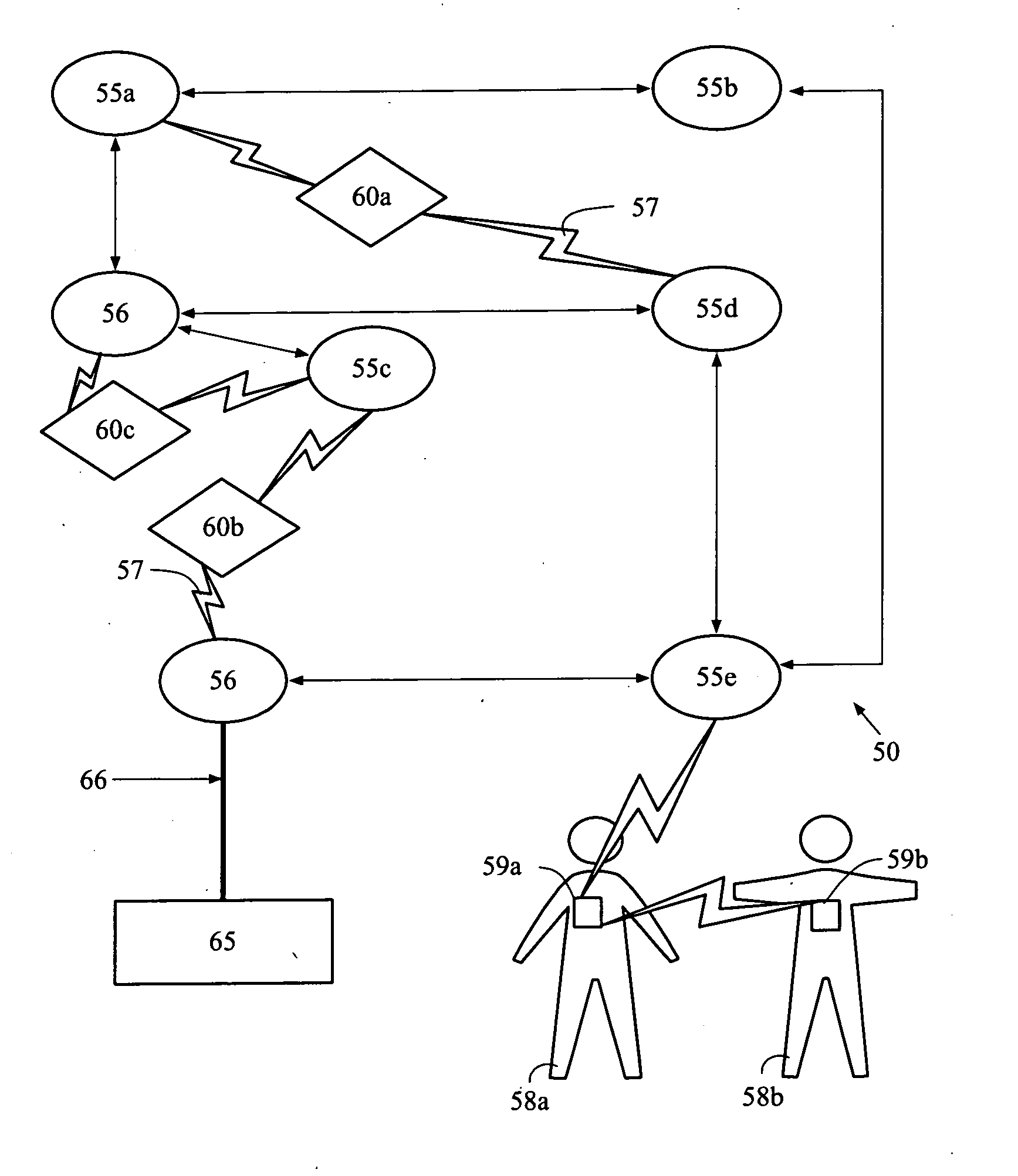
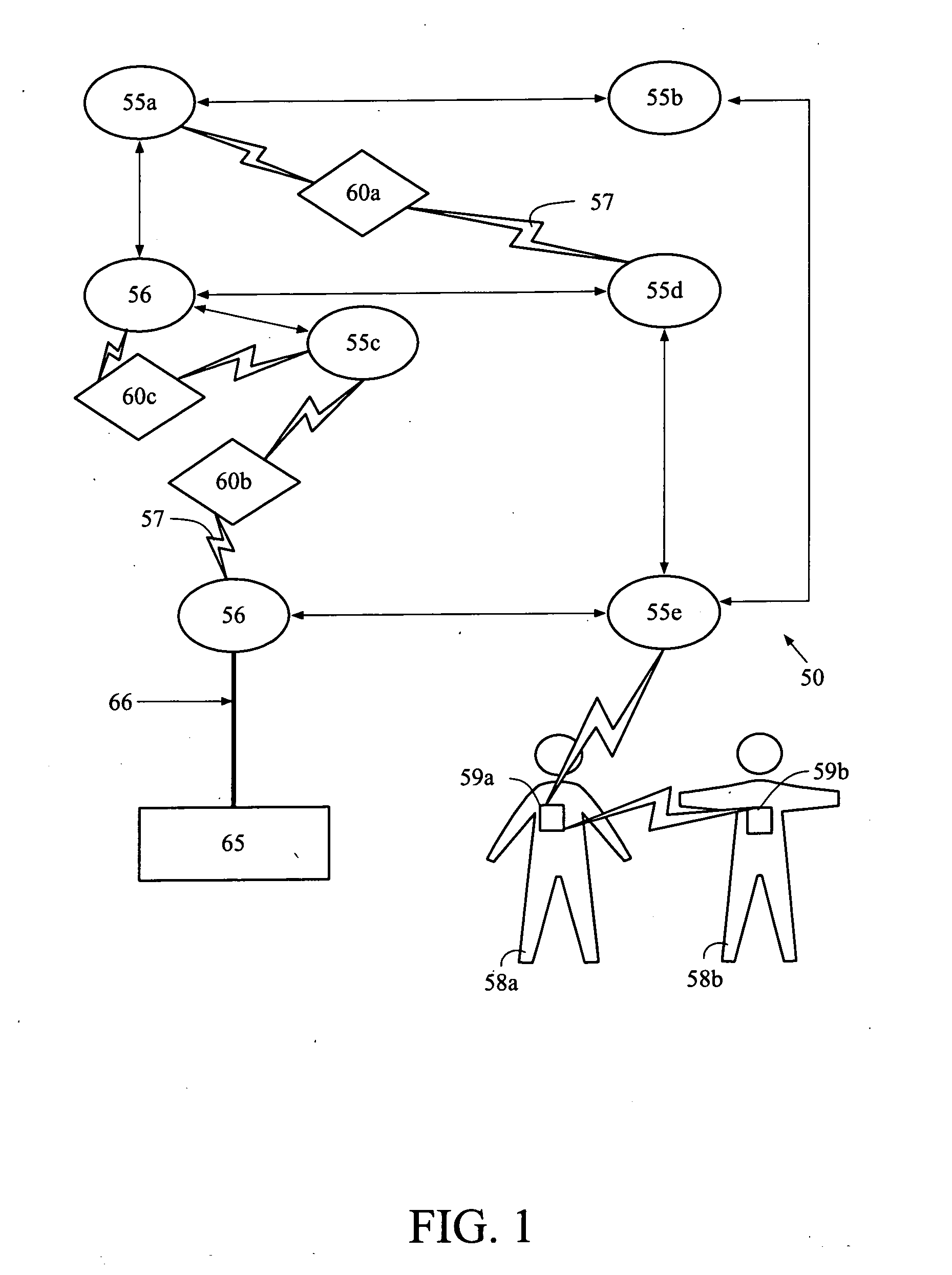
[0051]As shown in FIGS. 1-3, a system for tracking objects within a facility is generally designated 50. The system 50 is capable of analyzing an interaction between objects, individuals 58 and / or objects 100. The system 50 preferably includes a plurality of sensors 55, a plurality of bridges 56, a plurality of near-field communication devices 59, a plurality of tags 60, and at least one information engine 65. The sensors 55 form a mesh network for receiving signals from the near-field communication devices 59 and tags 60. One example of the components of the system 50 is disclosed in U.S. Pat. No. 7,197,326, for a Wireless Position Location And Tracking System, which is hereby incorporated by reference in its entirety. A more specific example of the sensors 55 is disclosed in U.S. Pat. No. 7,324,824, for a Plug-In Network Appliance, which is hereby incorporated by reference in its entirety.

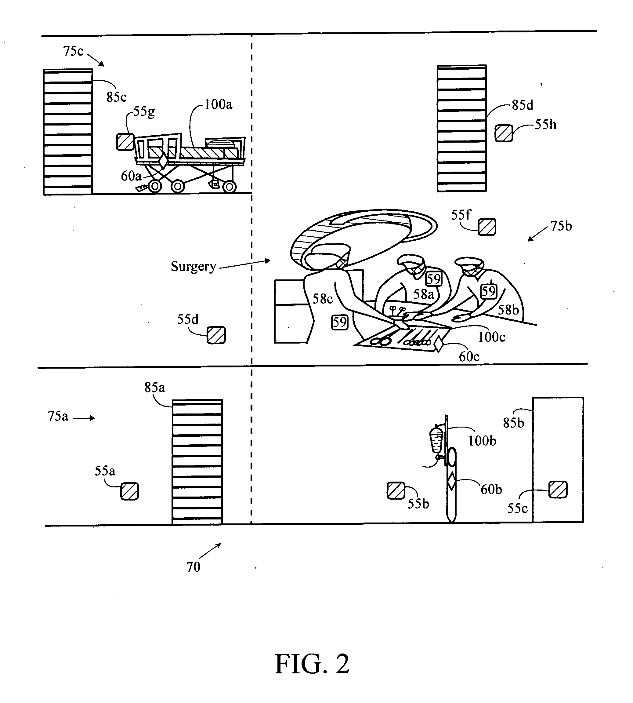
[0052]The system 50 is preferably employed at a facility 70 such as a business office, factor...


PUM


Abstract

The present invention provides a method and system to determining a near-field communication interaction in a wireless tracking mesh network. The present invention preferably utilizes near-field communication devices in conjunction with tracking tags to transmit signals for reception by sensors stationed throughout a facility which form a mesh network and forward the signals to an information engine for analysis.

Description

CROSS REFERENCES TO RELATED APPLICATIONS[0001]The present application claims priority to U.S. Provisional Patent Application No. 61 / 244,053, filed Sep. 20, 2009, which is hereby incorporated by reference in its entirety.STATEMENT REGARDING FEDERALLY SPONSORED RESEARCH OR DEVELOPMENT[0002]Not ApplicableBACKGROUND OF THE INVENTION[0003]1. Field of the Invention[0004]The present invention is related to wireless tracking systems and methods utilizing near-field communication devices. More specifically, the present invention relates to a system and method utilizing near-field communication devices for analyzing near-field communication interactions.[0005]2. Description of the Related Art[0006]Real-time knowledge of resources, whether the resources are assets or people, is becoming a necessary tool of many businesses. Real-time knowledge of the location, status and movement of crucial resources can allow a business to operate more efficiently and with fewer errors. However, many businesse...

Claims


Application Information

Patent Timeline
Patent Type & Authority Applications(United States)
IPC IPC(8): G06F7/04G06F17/00G06Q50/00H04L12/28H04W40/00
CPCG06Q10/08G06Q10/087H04B5/0087G06Q50/22H04B5/0031G06Q30/0283G16H40/67
Inventor PERKINS, MATTHEW R.TRUSCOTT, ANTHONY
Owner AWAREPOINT CORPORATION
Why Eureka
Try Eureka