Supercharge Your Innovation With Domain-Expert AI Agents!

Co-Location of a Pico eNB and Macro Up-Link Repeater

Inactive Publication Date: 2011-03-24
INTEL CORP
View PDF7 Cites 34 Cited by
  • Summary
  • Abstract
  • Description
  • Claims
  • Application Information

AI Technical Summary

Benefits of technology

[0008]In a preferred embodiment of the wireless communication system, user equipment (UE) is located within the service area, where the UE is configured for transmitting the signals to the repeater. The second base station further comprises a second base station antenna, where the repeater further comprises a repeater service antenna configured for communication with the UE. The transmission power of the UE preferably is established such that receiver desensitization of the second base station antenna is avoided. The repeater co-located with the second base station preferably further comprises the second base station antenna comprising the repeater service antenna. In an embodiment of the present invention, the repeater co-located with the second base station further comprises the second base station and the repeater each affixed to the same tower. The wireless communication system further comprising a plurality of additional base stations each configured for communication within a corresponding plurality of additional cells, wherein each additional cell is smaller than the first cell and is located within the first cell. A plurality of additional repeaters each co-located with a corresponding additional base station, wherein each additional repeater is configured for receiving signals within a corresponding service area and re-transmitting the received signals as a directed beam to the first base station. The service area preferably is a region in which the first base station receives signals emitted by the UE via the repeater that are greater than signals sent directly from the UE to the first base station. The second cell preferably is enclosed within the service area. In an embodiment, the wireless system comprises a Long Term Evolution (“LTE”) system, wherein the first base station comprises a macro evolved node B (eNB), the repeater comprises a macro up-link repeater, and the second base station comprises a pico eNB.
[0009]In another aspect, the present invention provides a method for wireless communication, comprising receiving signals C01b emitted by a first 501 user equipment (UE) by a first base station 530 within a service area 530a receiving signals C01a emitted by a first 501 user equipment (UE) by a repeater 540 within a service area 540a using a first antenna 425, re-transmitting the received signals as a directed beam 541 using a second antenna 421 to a first base station 530, establishing combined signal level of received signals from UE 501 and from repeater 540 at first base station 530, and reducing the transmission power of the first UE 501 such that receiver of Pico eNB 520 desensitization is avoided based on said combined received signal levels.

Problems solved by technology

However, interference between the macro and pico base stations must be managed.

Method used


Image

  • Co-Location of a Pico eNB and Macro Up-Link Repeater
  • Co-Location of a Pico eNB and Macro Up-Link Repeater
  • Co-Location of a Pico eNB and Macro Up-Link Repeater

Examples


Embodiment Construction

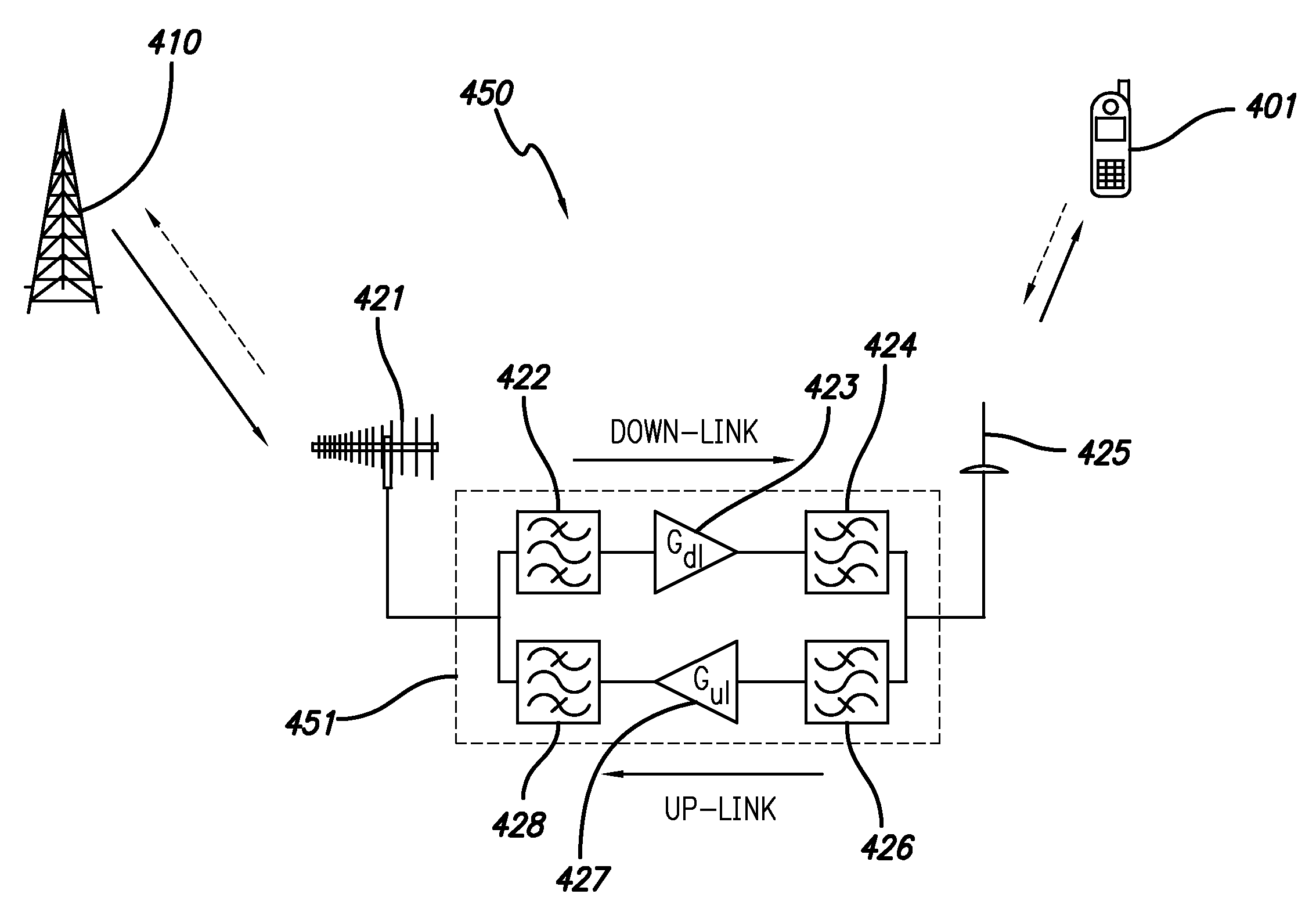
[0023]The present invention prevents the desensitization of the receiver of a base station having lower power by co-locating a repeater with the base station having lower power. In an embodiment of the present invention, an User Equipment (“UE”) communicates with a base station having higher power via the repeater. In one or more embodiments of the present invention, the UE communicates with the repeater with reduced transmission power as compared to the transmission power required for the UE to communicate directly with the base station having higher power. As a result, the UE does not desensitize the receiver of the base station having lower power. The repeater has a donor antenna that radiates a highly directional beam to the macro eNB.

[0024]One or more embodiments of the present invention is directed to a system for improving wireless networks and is not necessarily based on one or more technical specifications. For the purposes of illustrating examples of the present invention,...


PUM


Abstract

A wireless communication system and method comprising co-location of a pico evolved node B (“eNB”) and a macro up-link repeater is disclosed. User Equipment (“UE”) communicates with a macro eNB via the up-link repeater with reduced transmission power as compared to the transmission power required for the UE to communicate directly with the macro eNB. As a result, the UE does not desensitize the pico eNB receiver. The up-link repeater comprises a donor antenna that radiates a highly directional beam to the macro eNB.

Description

RELATED APPLICATION INFORMATION[0001]The present application claims priority under 35 U.S.C. Section 119(e) to U.S. Provisional Patent Application Ser. No. 61 / 245,194 filed Sep. 23, 2009, the disclosure of which is incorporated herein by reference in its entirety.BACKGROUND OF THE INVENTION[0002]1. Field of the Invention[0003]The present invention relates in general to radio communication systems for wireless networks. More particularly, the invention is directed to wireless heterogeneous cellular networks.[0004]2. Description of the Prior Art and Related Background Information[0005]Heterogeneous networks combine macro and pico base stations within a wireless communication system. In general, locating several pico base stations within the cell coverage of a macro base station will increase the capacity of the network. However, interference between the macro and pico base stations must be managed.[0006]Accordingly, a need exists to improve heterogeneous network operation.SUMMARY OF T...

Claims


Application Information

Patent Timeline
IPC IPC(8): H04B7/14H04W88/00
CPCH04B7/2606Y02B60/50H04W16/32H04W16/26Y02D30/70
Inventor BRAITHWAITE, RICHARD NEIL
Owner INTEL CORP
Features
  • R&D
  • Intellectual Property
  • Life Sciences
  • Materials
  • Tech Scout
  • Unparalleled Data Quality
  • Higher Quality Content
  • 60% Fewer Hallucinations
Learn More