Drive unit

a technology of drive unit and drive shaft, which is applied in the direction of gearing, hoisting equipment, cycles, etc., can solve the problem of reducing the ripping force, and achieve the effect of efficient transmission

Active Publication Date: 2011-03-24
HONDA MOTOR CO LTD
View PDF50 Cites 43 Cited by
  • Summary
  • Abstract
  • Description
  • Claims
  • Application Information

AI Technical Summary

Benefits of technology

[0016]According to the third aspect of the invention, the grooves are formed such that the interval between adjacent grooves is narrower than the intervals between adjacent first drive rollers and between adjacent second drive rollers. Consequently, since the first holder (second holder) rotates with respect to any given driven roller, when there is intermittent contact between adjacent first drive

Problems solved by technology

However, there is a possibility that the gripping force will decrease when the d

Method used


Image

  • Drive unit
  • Drive unit
  • Drive unit

Examples


Embodiment Construction

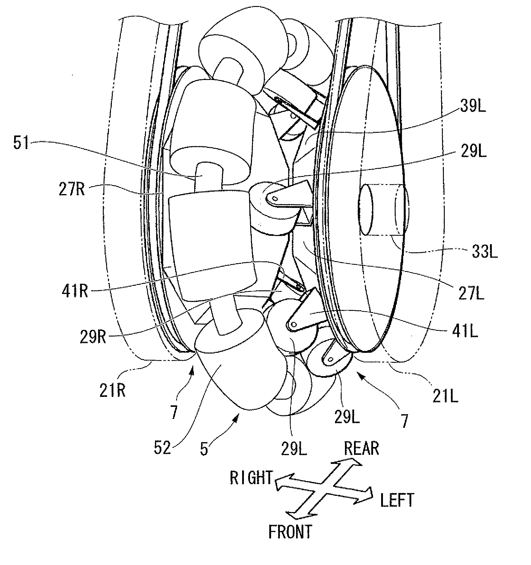
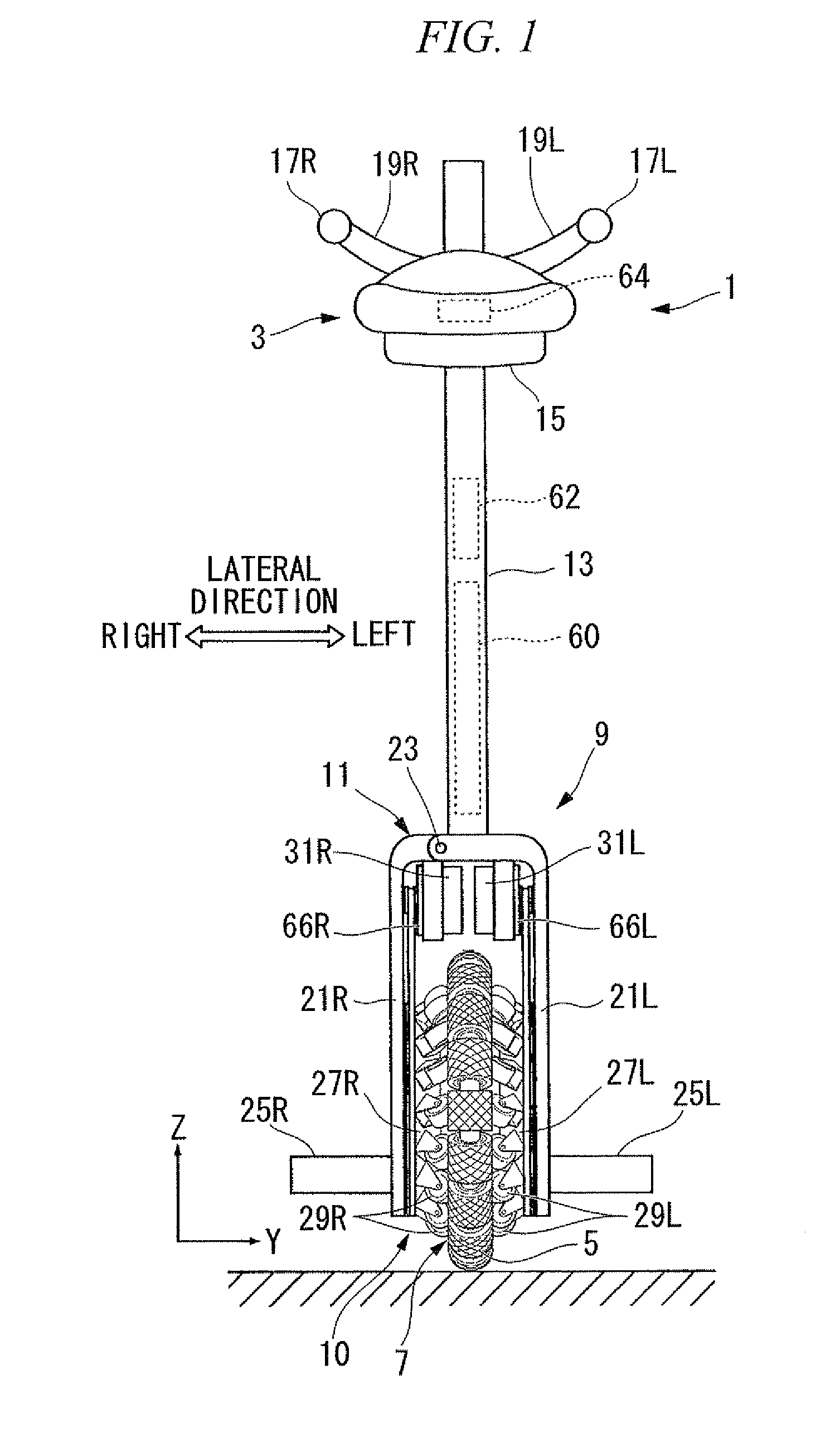
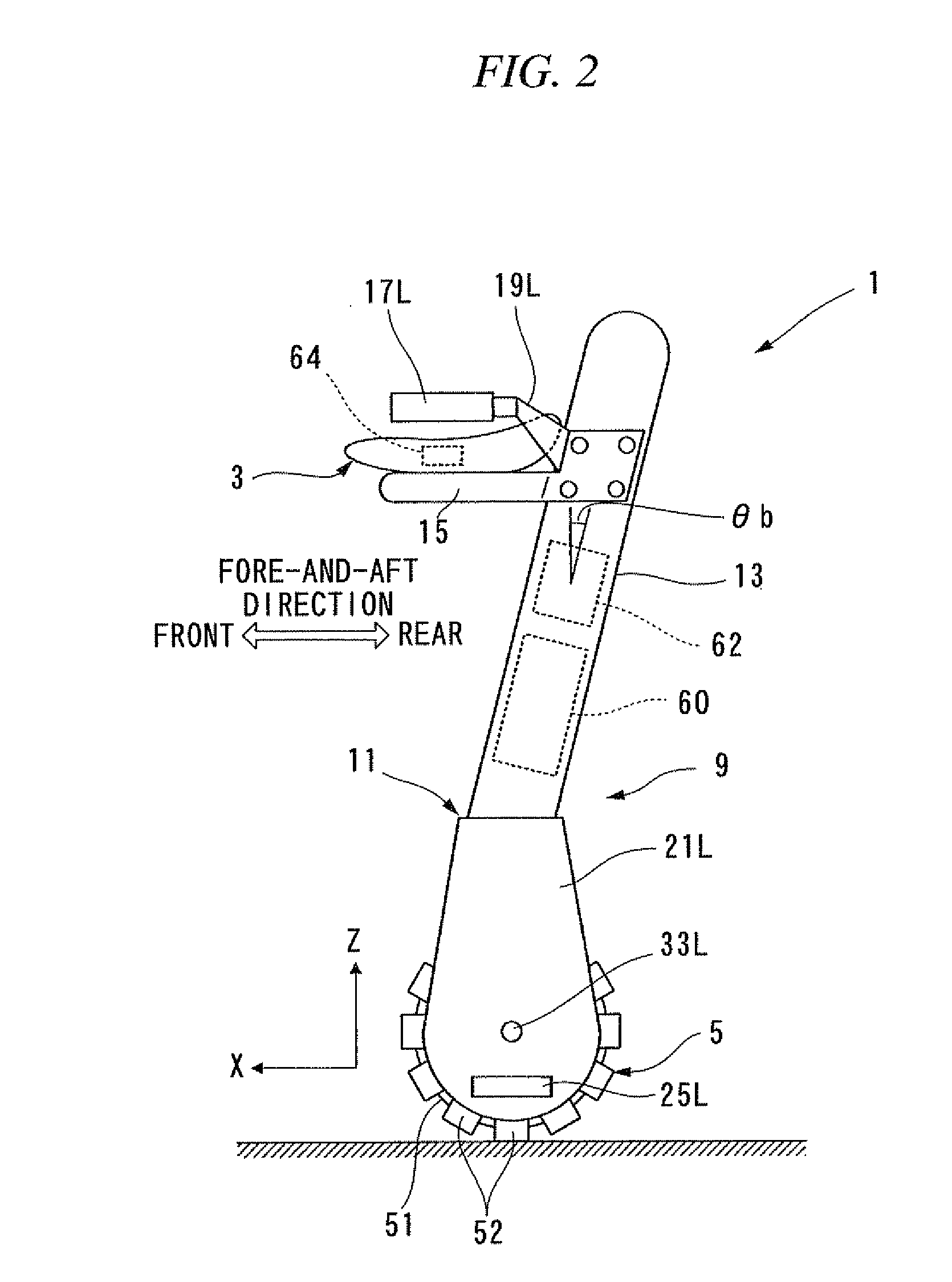
[0029]Subsequently, an embodiment of the drive unit according to the present invention will be explained based on FIG. 1 to FIG. 12. In this embodiment, an omnidirectional vehicle which is an inverted pendulum type will be described.

[0030]As shown in FIG. 1 and FIG. 2, an omnidirectional vehicle 1 in this embodiment is a moving body which is an inverted pendulum type and including a payload supporting part 3 for a passenger who rides on the vehicle (operator), a main wheel 5 that can move on the floor surface omnidirectionally (in all directions within two dimensions, including the fore-and-aft direction and the lateral direction) while contacting the floor surface, an actuator 7 that applies power for driving the main wheel 5 to the main wheel 5, and a base 9 which the payload supporting part 3, the main wheel 5, and the actuator 7 are installed to. The main wheel 5 and the actuator 7 are constituted as a drive unit 10.

[0031]In the explanation of this embodiment, the directions of ...


PUM

PropertyMeasurementUnit
Angleaaaaaaaaaa

Abstract

A drive unit includes a main wheel having an annular member, and a plurality of driven rollers that are rotatably attached to the annular member, a plurality of first drive rollers and a plurality of second drive rollers, which are provided with the annular member between them and arranged such that they make contact with the outer peripheral faces of the driven rollers, a first holder and a second holder, which are arranged with the annular shaft between them and respectively hold the plurality of first drive rollers and the plurality of second drive rollers while allowing them to rotate, and a first drive unit and a second drive unit that rotationally drive the first holder and the second holder respectively; grooves are formed in the outer peripheral faces of the driven rollers at an angle to the circumferential direction thereof.

Description

BACKGROUND OF THE INVENTION[0001]1. Field of the Invention[0002]The present invention relates to a drive unit. More specifically, it relates to a drive unit provided in an omnidirectional vehicle.[0003]Priority is claimed on Japanese Patent Application No. 2009-218172 filed Sep. 18, 2009, the content of which is incorporated herein by reference.[0004]2. Description of Related Art[0005]An omnidirectional vehicle that can move omnidirectionally on a floor surface (i.e. in all directions within two dimensions) was proposed by the present applicants in, for example, International Publication No. 2008 / 132778 and International Publication No. 2008 / 132779. In the omnidirectional vehicles in International Publication Nos. 2008 / 132778 and 2008 / 132779, a ball-shaped, or wheel-shaped, or crawler-shaped main wheel that can move omnidirectionally on the floor surface while contacting the floor surface, and an actuator that includes an electric motor for driving the main wheel, and the like, are ...

Claims


Application Information

Patent Timeline
IPC IPC(8): F16H13/08
CPCB60B19/003B60B19/125B60B2200/47B62K3/007B60B2360/50B62K1/00B60B2360/348B62K11/007
Inventor TAKENAKA, TORUGOMI, HIROSHIKOBASHI, SHINICHIROKOYAMA, TAIJISASAKI, MASAOIZUMI, HIDEHARUKUWABARA, KAZUYA
Owner HONDA MOTOR CO LTD
Why Eureka
Try Eureka