Cyclic Heat Therapy Device

a heat therapy device and cycle technology, applied in the field of cycle heat therapy devices, can solve the problems of slow cycle time, large system, bulky, expensive,

Inactive Publication Date: 2011-03-24
MOORE JOSHUA JOHN EDWARD
View PDF4 Cites 39 Cited by
  • Summary
  • Abstract
  • Description
  • Claims
  • Application Information

AI Technical Summary

Problems solved by technology

Large hot and cold baths have been used to provide contrast therapy for athletes but these systems are large, expensive, and there are patient compliance issues associated with moving persons from hot to cold baths and with non-localized treatment of the affected area of the body.
Smaller systems are available that use heated or cooled water and circulate the fluids through tubes around the afflicted areas of the body to provide cyclic relief, but these are bulky, expensive, and have slow cycling times due to large volume fluid changeover.
All of these cyclic contrast therapy systems have disadvantages.
One common limitation to heat treatment using the present devices is the need for prepared devices.
This requires freezer space and precognitive thought that injury may occur.
The use of cold packs and ice bags also results in significant condensation and moisture build up.
The chemical reaction is not reversible and its operating life is limited to the length of the chemical reaction.
Once the reaction is completed the bags are useless and must be discarded.
There are some heat blankets and wraps available that can provide hot therapy, but there is no portable device available that can produce both hot and cold therapy in cyclic succession.
With the above mentioned examples there is no way to cycle between hot and cold quickly without manually alternating between heating and cooling devices.
Similarly, there is poor control over the temperatures and durations that the devices operate.

Method used


Image

  • Cyclic Heat Therapy Device
  • Cyclic Heat Therapy Device
  • Cyclic Heat Therapy Device

Examples


Embodiment Construction

will be rendered by reference to example embodiments thereof which are disclosed in the appended drawings. It is appreciated that these drawings depict only example embodiments of the invention and are therefore not to be considered limiting of its scope. Aspects of the invention will be described and explained with additional specificity and detail through the use of the accompanying drawings in which:

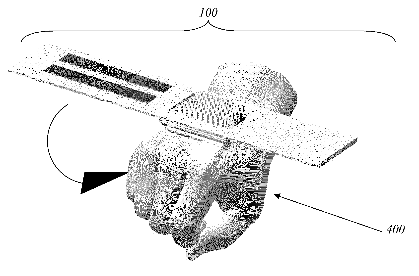
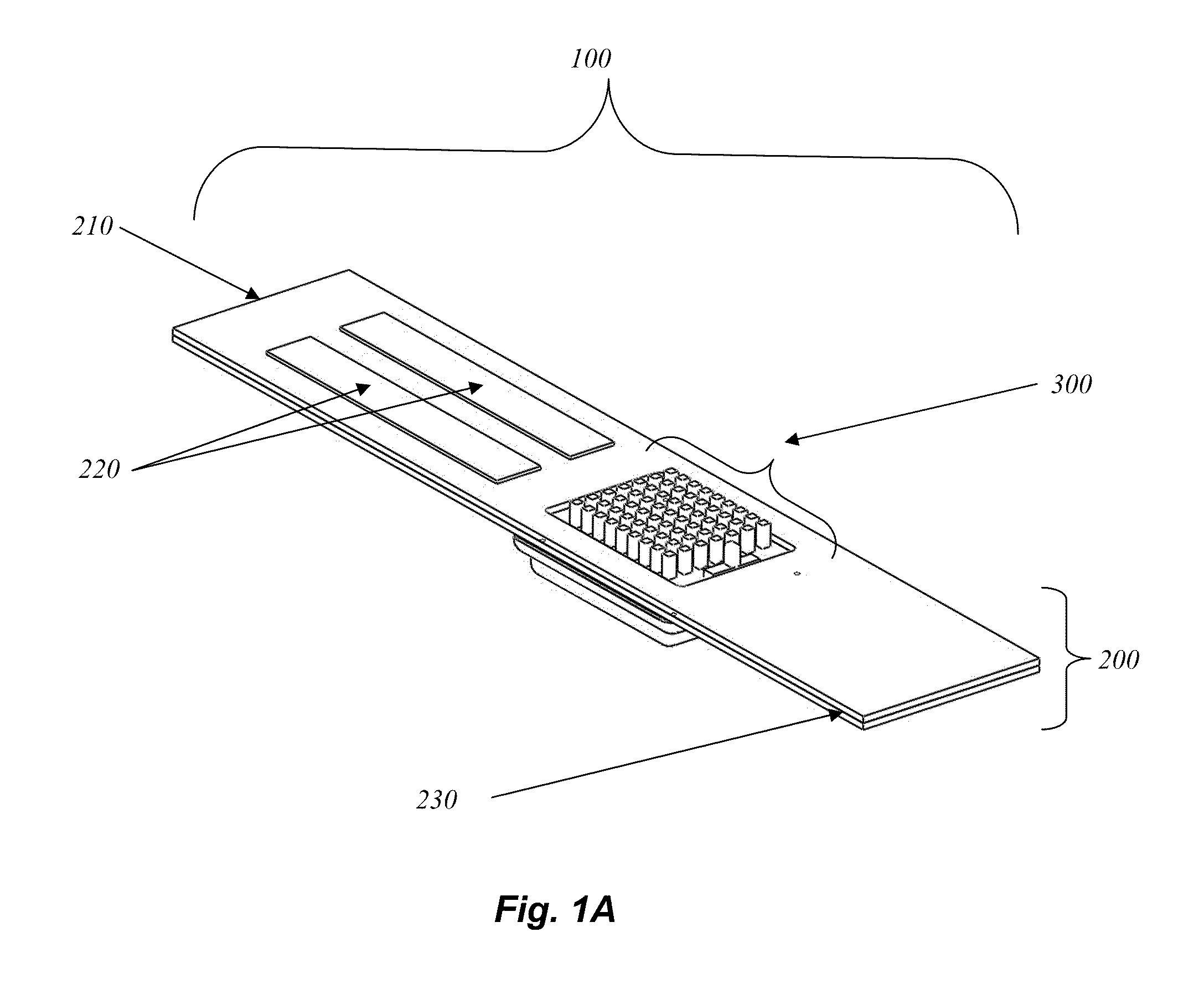
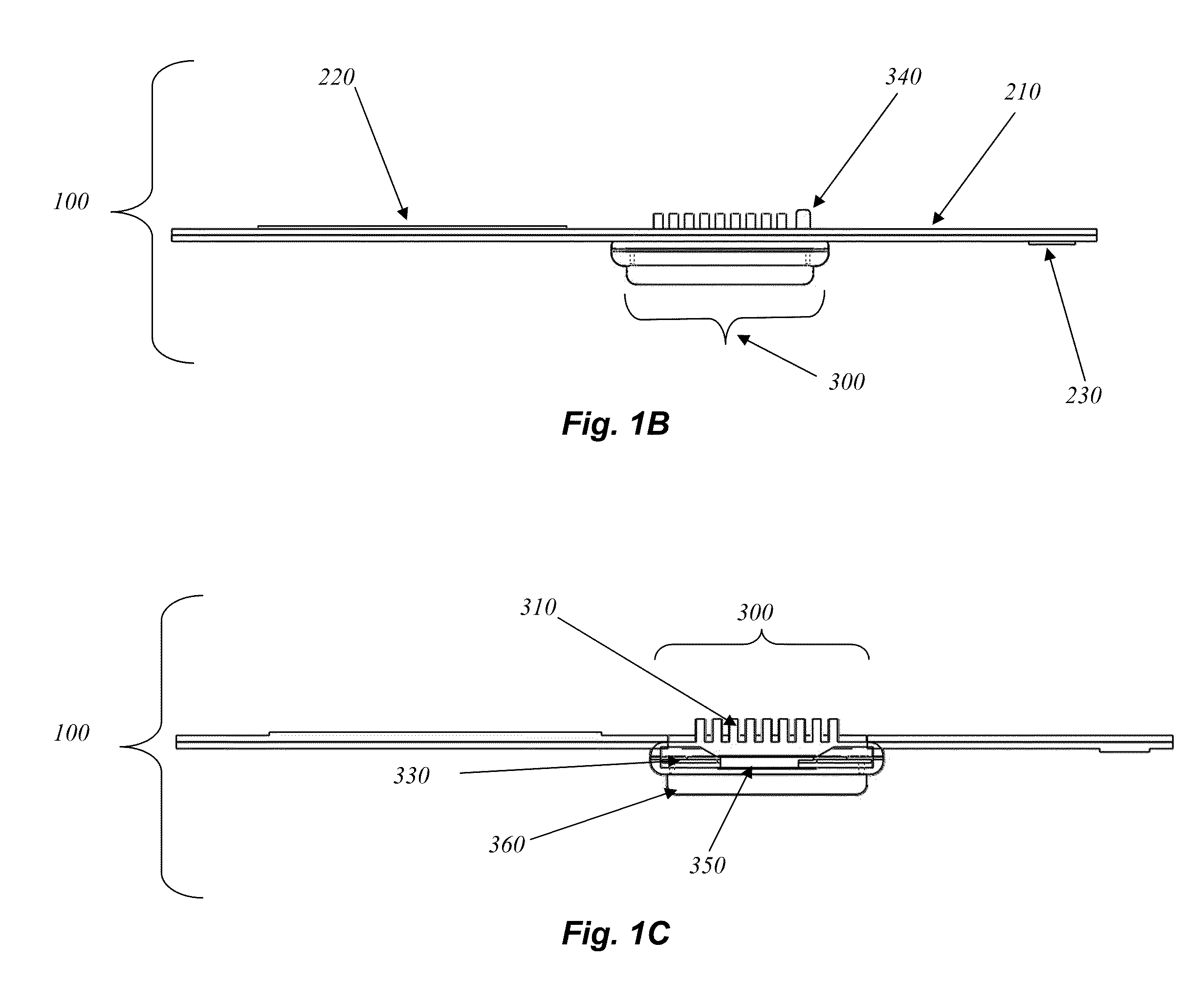
[0005]FIGS. 1A-1D disclose various views of an example cyclic heat therapy device shown with an example wrap. More specifically FIG. 1D shows an exploded view of an example cyclic heat therapy device;

[0006]FIGS. 2A-2B disclose various views of an example cyclic heat therapy device from FIG. 1 showing the cyclic heat therapy device with the wrap removed. More specifically FIG. 2B shows an exploded view of an example cyclic heat therapy device; and

[0007]FIG. 3A discloses a view of an example cyclic heat therapy device from FIGS. 1 and 2 showing the device in application on a human hand....


PUM


Abstract

The therapy device enables the automatic application of customized and well controlled contrast therapy to localized areas of human and animal bodies. An electronic control circuit is used in conjunction with heat dissipating and heat absorbing surfaces to control the operation of a thermoelectric cooling module (TEC) to enable the administering of localized contrast therapy on human and animal bodies. The use of temperature sensors, timing circuits, and microprocessors in connection with the TEC and heat absorbing and dissipating surfaces allows precise control of the applied temperature and the time duration for cooling and heating cycles. The device is programmable and is capable of automatic cycling between desired heating and cooling temperatures for variable lengths of time.

Description

CROSS-REFERENCE TO RELATED APPLICATIONS[0001]This application claims the benefit of U.S. Provisional Patent Application Ser. No. 61 / 245,651 filed Sept. 24, 2009 and entitled CYCLIC HEAT THERAPY DEVICE, the contents of which are herein incorporated by reference in their entirety.BACKGROUND OF THE INVENTION[0002]Many injuries to the human body such as sprains, damaged ligaments or tendons, torn or bruised muscles, aching joints, and post surgery recoveries are commonly treated with the application of hot and or cold therapy. Such therapy involves the application of heat or removal of heat to the afflicted area of the human body. This temperature treatment helps to reduce swelling, pain, and promote healing. In many instances it is also recommended that cyclic heat treatment, hot-cold-hot-cold, or cold-hot-cold-hot-cold-hot or similar patterns offers superior health benefits over that of constant heat or constant cold treatments. In the past heat treatments have been applied using hot ...

Claims


Application Information

Patent Timeline
Patent Type & Authority Applications(United States)
IPC IPC(8): A61F7/00
CPCA61F7/007A61F2007/0093A61F2007/0096A61F2007/0296A61F2007/0228A61F2007/0295A61F2007/0226
Inventor MOORE, JOSHUA JOHN EDWARD
Owner MOORE JOSHUA JOHN EDWARD
Why Eureka
Try Eureka