Membrane-Coupled Ultrasonic Probe System for Detecting Flaws in a Tubular

a membrane-coupled, ultrasonic probe technology, applied in the direction of instruments, specific gravity measurement, and analysis of fluids using sonic/ultrasonic/infrasonic waves. it can solve the problem that single phased array probes can not detect flaws in all orientations, and achieve the effect of quick and easy attachment and removal

Active Publication Date: 2011-03-31
NAT OILWELL VARCO LP
View PDF18 Cites 43 Cited by
  • Summary
  • Abstract
  • Description
  • Claims
  • Application Information

AI Technical Summary

Benefits of technology

[0012]The tilting of the probe is achived by a beam angle position block that is attached to the bottom of the scanner housing and the beam angle position block rides on the pipe outside surface. The beam angle position block can be quickly and easily attached and detached from the housing. Ultrasound from the phased array probe is coupled into the pipe through direct contact between a membrane on the scanner and the pipe outside surface.

Problems solved by technology

A single phased array probe still can not detect flaws in all orientations in current inspection systems.

Method used


Image

  • Membrane-Coupled Ultrasonic Probe System for Detecting Flaws in a Tubular
  • Membrane-Coupled Ultrasonic Probe System for Detecting Flaws in a Tubular
  • Membrane-Coupled Ultrasonic Probe System for Detecting Flaws in a Tubular

Examples


Embodiment Construction

[0047]The present invention will now be described in detail, with reference to the accompanying drawings. In this detailed description, numerous specific details may be set forth in order to provide a thorough understanding of the invention. However, it will be apparent to one skilled in the art when the invention may be practiced without some or all of these specific details. In other instances, well-known features and / or process steps may not be described in detail so as not to unnecessarily obscure the invention. In addition, similar reference numerals may be used to identify common or similar elements.

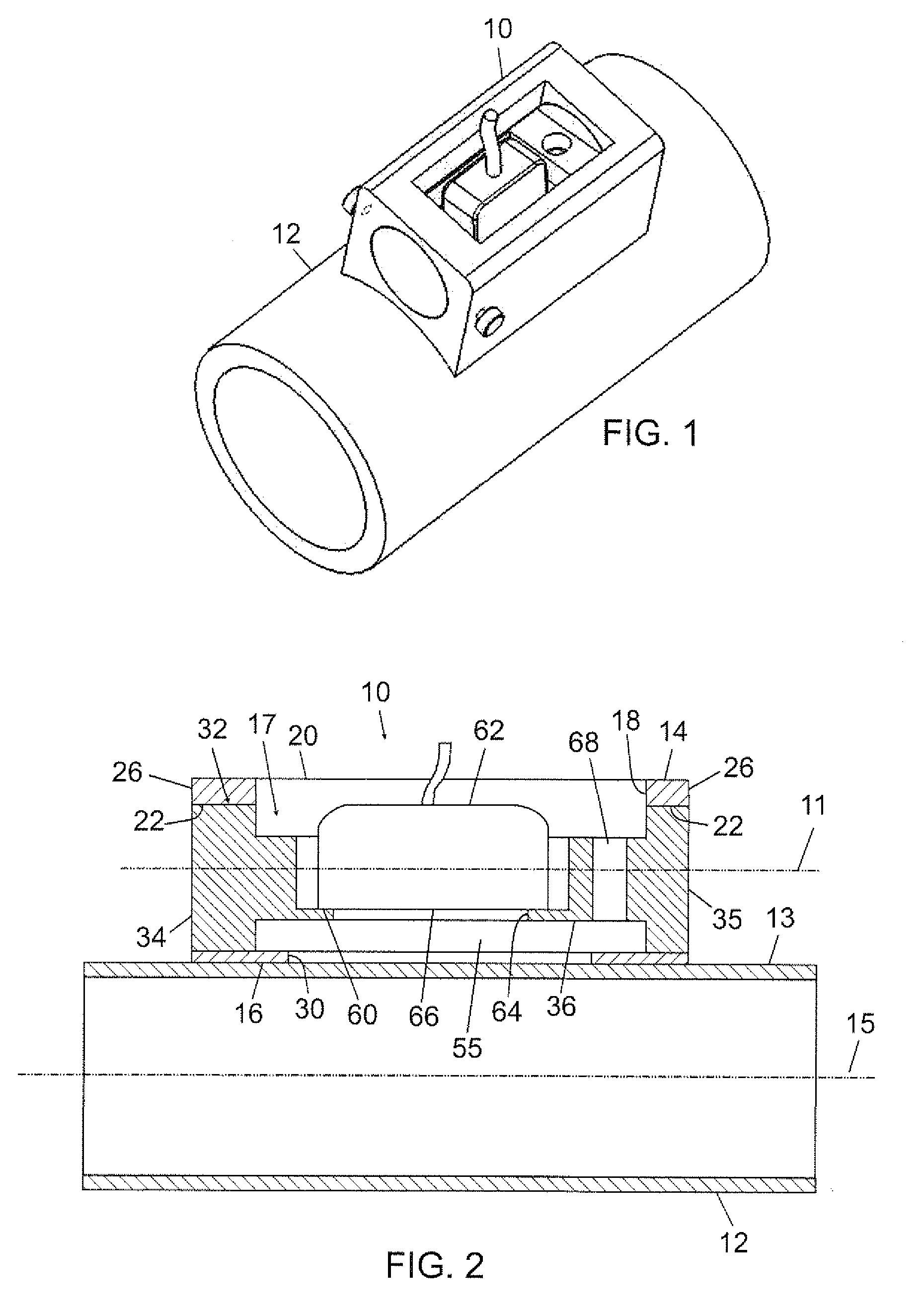
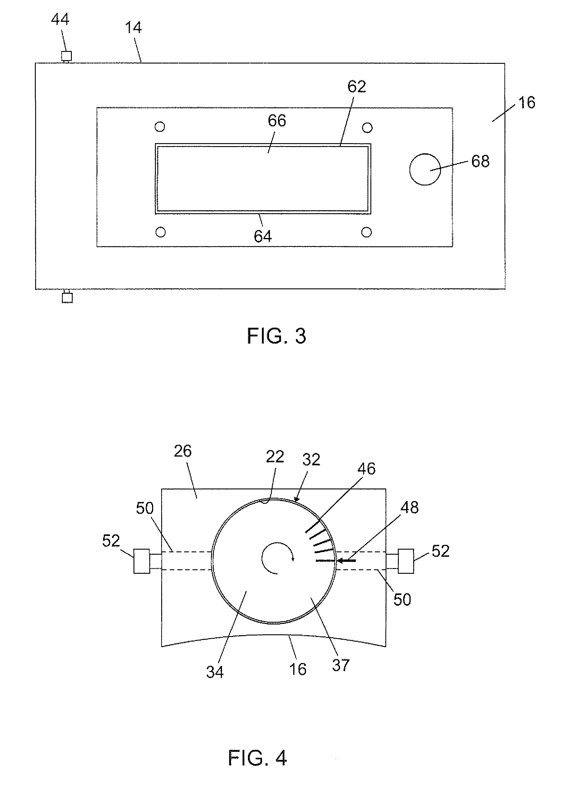
[0048]The present invention relates to an ultrasonic testing system capable of flexibly orienting a one-dimensional (but not limited to a one-dimensional) phased array probe in order to detect flaws in any desired direction, (i.e. transverse, longitudinal, or oblique) relative to the axial axis of a tubular.

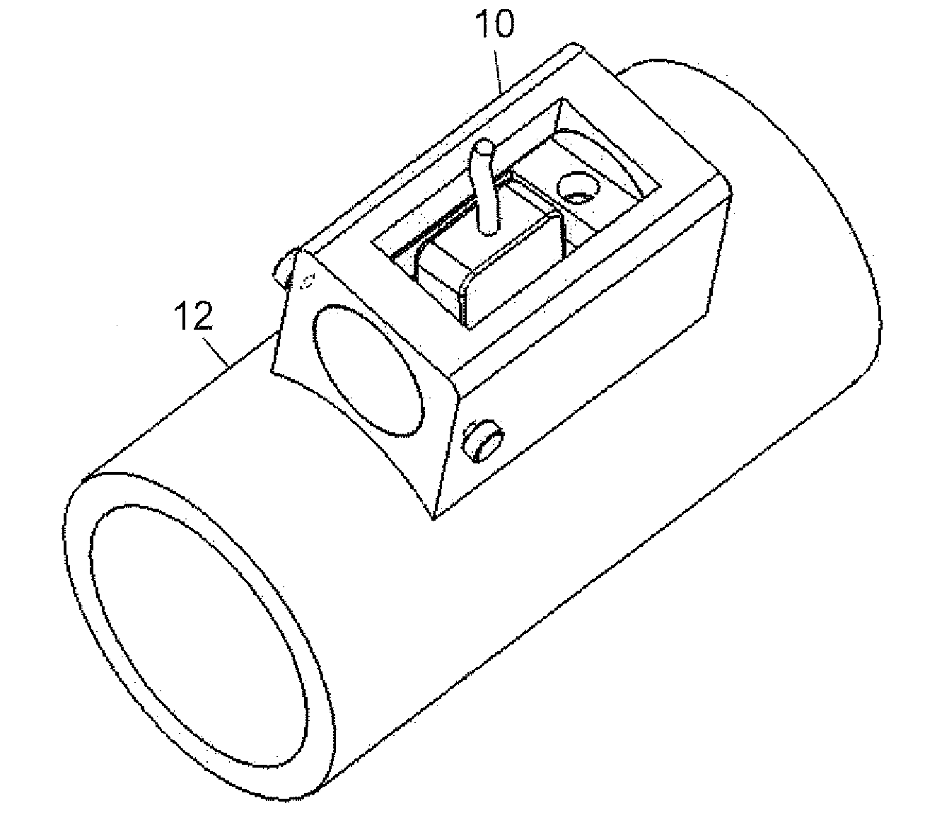
[0049]FIG. 1 shows an ultrasonic testing system including an ultrasonic pro...


PUM

PropertyMeasurementUnit
widthaaaaaaaaaa
widthaaaaaaaaaa
angleaaaaaaaaaa

Abstract

An ultrasonic probe apparatus for detecting flaws in a tubular includes a probe housing. The probe housing has an axial axis, a central cavity lying along the axial axis, and a bottom face adapted for placement on the tubular. The bottom face of the probe housing has an opening in the middle. A probe support is disposed within the central cavity and rotatable about the axial axis of the probe housing. An ultrasonic probe is mounted on the probe support and has a scanning face exposed to the opening of the bottom face of the probe housing, and may be coupled to the pipe with a liquid acoustic couplent medium.

Description

CROSS-REFERENCE TO RELATED APPLICATIONS[0001]This application claims priority from, and is a continuation-in-part of presently pending U.S. patent application Ser. No. 12 / 568,737, filed on 29 Sep. 2009, which is incorporated by reference herein for all it contains.BACKGROUND OF THE INVENTION [0002]1. Field of the Invention[0003]The present disclosure relates generally to an ultrasonic probe apparatus, an ultrasonic probe system, and an ultrasonic probe method for detecting the presence of structural and material flaws in a tubular. In particular, the disclosure relates to an ultrasonic probe apparatus which employs a single, handheld scanner and a single ultrasonic phased array probe to detect structural and material flaws, i.e. wall reduction, cracks or manufacturing defects, etc., which may occur to a tubular being manufactured or after being in operation. In particular, the probe apparatus is designed and operated in a manner to specifically determine the thickness of a wall and ...

Claims


Application Information

Patent Timeline
Patent Type & Authority Applications(United States)
IPC IPC(8): G01N29/04
CPCG01N29/221G01N29/262G01N2291/2634G01N29/28G01N2291/106G01N29/265
Inventor LAM, CLIVE C.GUO, YANMINGLOGAN, KEVIN D.YUAN, QINGSHAN
Owner NAT OILWELL VARCO LP
Why Eureka
Try Eureka