Liquid discharge apparatus and method for producing the same

a technology of liquid discharge apparatus and liquid discharge, which is applied in the direction of lighting and heating apparatus, combustion types, coatings, etc., can solve the problems of inability to properly adjust the force of pressing the land against the terminal, excessive squashing or crushing of the terminal, and inability to operate the driving section. to achieve the effect of stabilizing the operation of the driving section, and avoiding electrical connection failur

Active Publication Date: 2011-03-31
BROTHER KOGYO KK
View PDF2 Cites 2 Cited by
  • Summary
  • Abstract
  • Description
  • Claims
  • Application Information

AI Technical Summary

Benefits of technology

[0007]The present invention has been made in order to solve the foregoing problem, an object of which is to provide a liquid discharge apparatus and a method for producing the same wherein it is possible to avoid the inhibition of the operation of the driving section and it is possible to avoid the electrical connection failure between the land and the terminal.
[0014]In this procedure, the thermally expandable members may be heated by, for example, the heater. Then, the heater may be allowed to abut against at least the areas in which the thermally expandable members are arranged, of the surface of the wiring board disposed on the side opposite to the side of the liquid discharge head, and the heater may be fixedly held. Therefore, when the thermally expandable members are heated, the thermally expandable members can be expanded toward the side opposite to the heater side (i.e., toward the terminal side). The lands can be reliably pushed to abut against the terminals by means of the thermally expandable members. When the terminals are formed of the thermosetting adhesive, the thermally expandable members and the thermosetting adhesive may be heated by the heater so that the thermosetting adhesive is cured after the thermally expandable members are expanded to bring the lands in contact under pressure with the terminals. Therefore, the “connecting the lands and the terminals electrically and physically” and the “curing the thermosetting adhesive” can be performed easily and quickly in one step.
[0021]In this arrangement, the lands are allowed to abut against the terminals by being pushed or pressed by the thermally expandable members. Therefore, the lands and the terminals can be reliably brought in contact with each other, and it is possible to avoid the electrical connection failure between the lands and the terminals. Further, the lands are extruded toward the liquid discharge head as compared with the surroundings thereof by being pushed or pressed by the thermally expandable members, and the lands are allowed to abut against the terminals. Therefore, it is possible to reliably prevent the surroundings of the lands from being brought in contact with the driving areas of the liquid discharge head.
[0022]According to the present teaching, the lands of the wiring board can be pushed to abut against the terminals by means of the thermally expandable members while securing the space between the driving areas and the wiring board. Therefore, it is possible to avoid the electrical connection failure between the lands and the terminals. Further, it is possible to prevent any part of the wiring board from being brought in contact with the driving areas. It is possible to stabilize the operation of the driving sections.

Problems solved by technology

However, it is not easy to appropriately adjust the force for pressing the land against the terminal.
If the force is too strong, the terminal is excessively squashed or crushed.
Therefore, it is feared that any portion of the flexible wiring board other than the land may be brought in contact with the surface of the ink-jet head, and the operation of the driving section may be inhibited.
On the other hand, if the force is too weak, it is impossible to sufficiently secure the contact area between the land and the terminal.
Therefore, it is feared that the electrical connection failure may be caused.

Method used


Image

  • Liquid discharge apparatus and method for producing the same
  • Liquid discharge apparatus and method for producing the same
  • Liquid discharge apparatus and method for producing the same

Examples


first embodiment

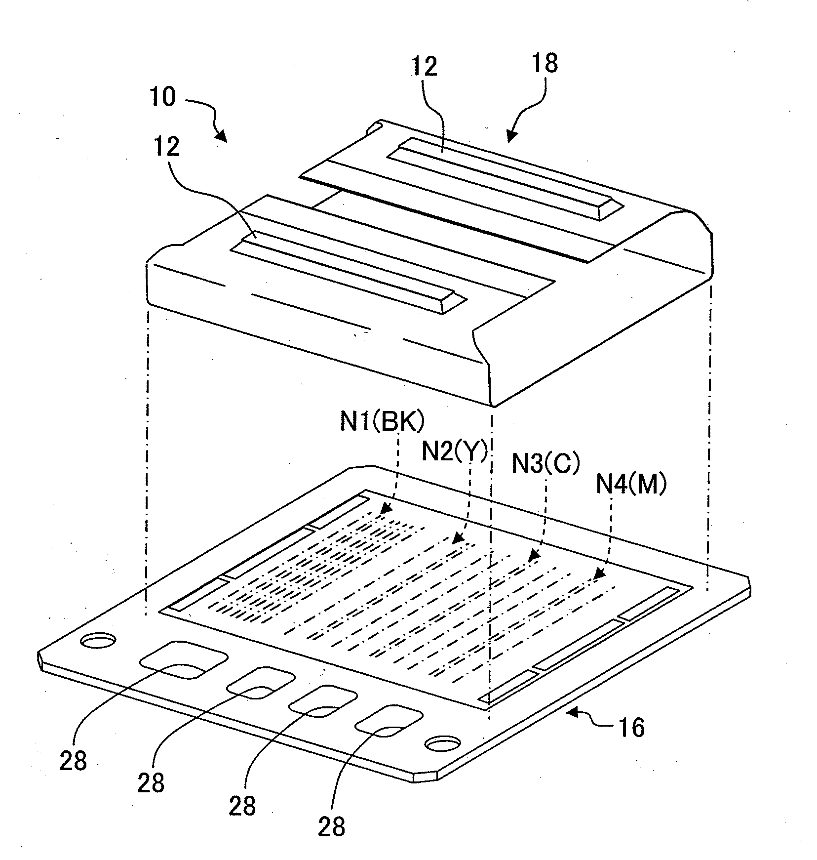
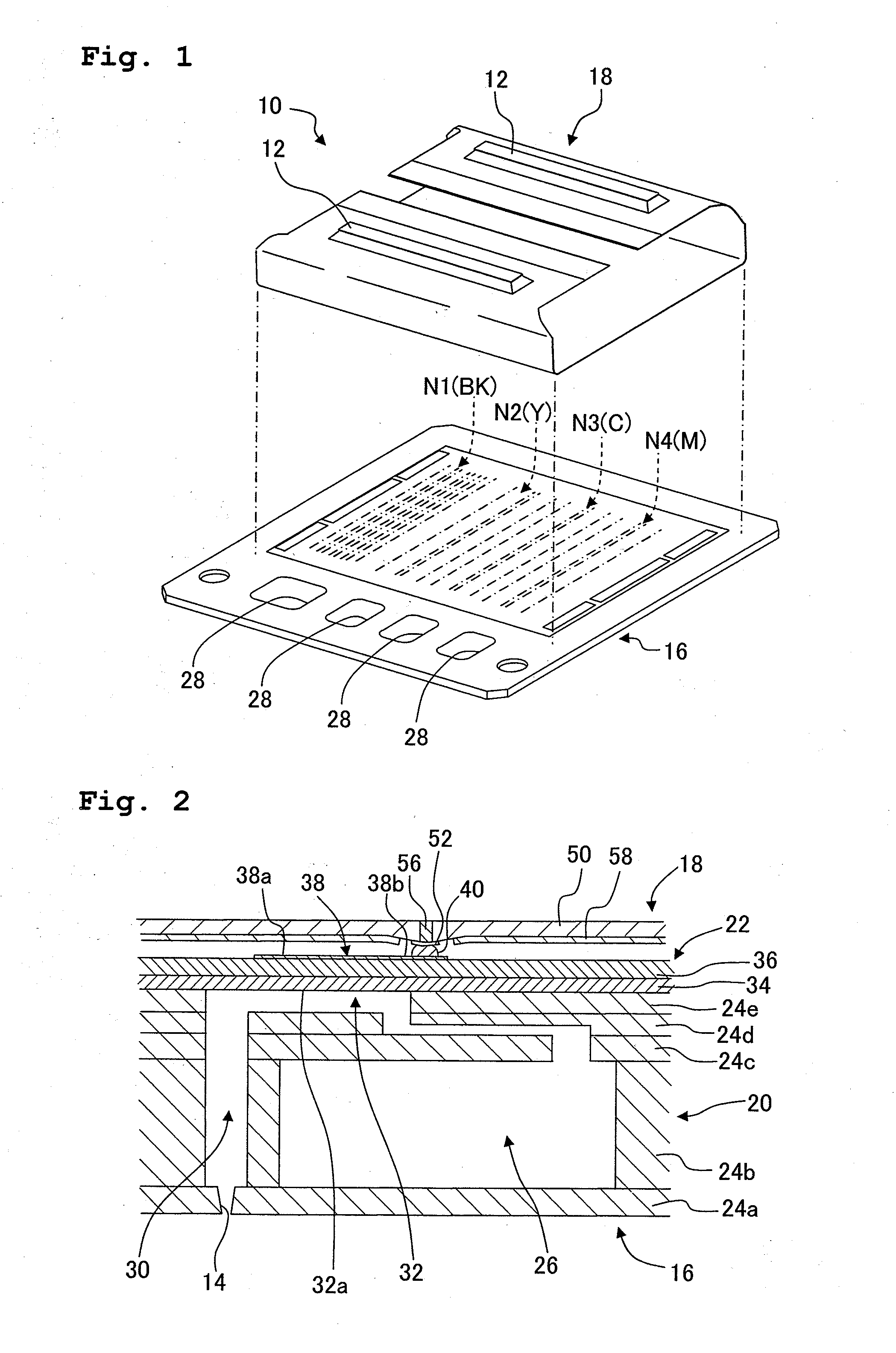
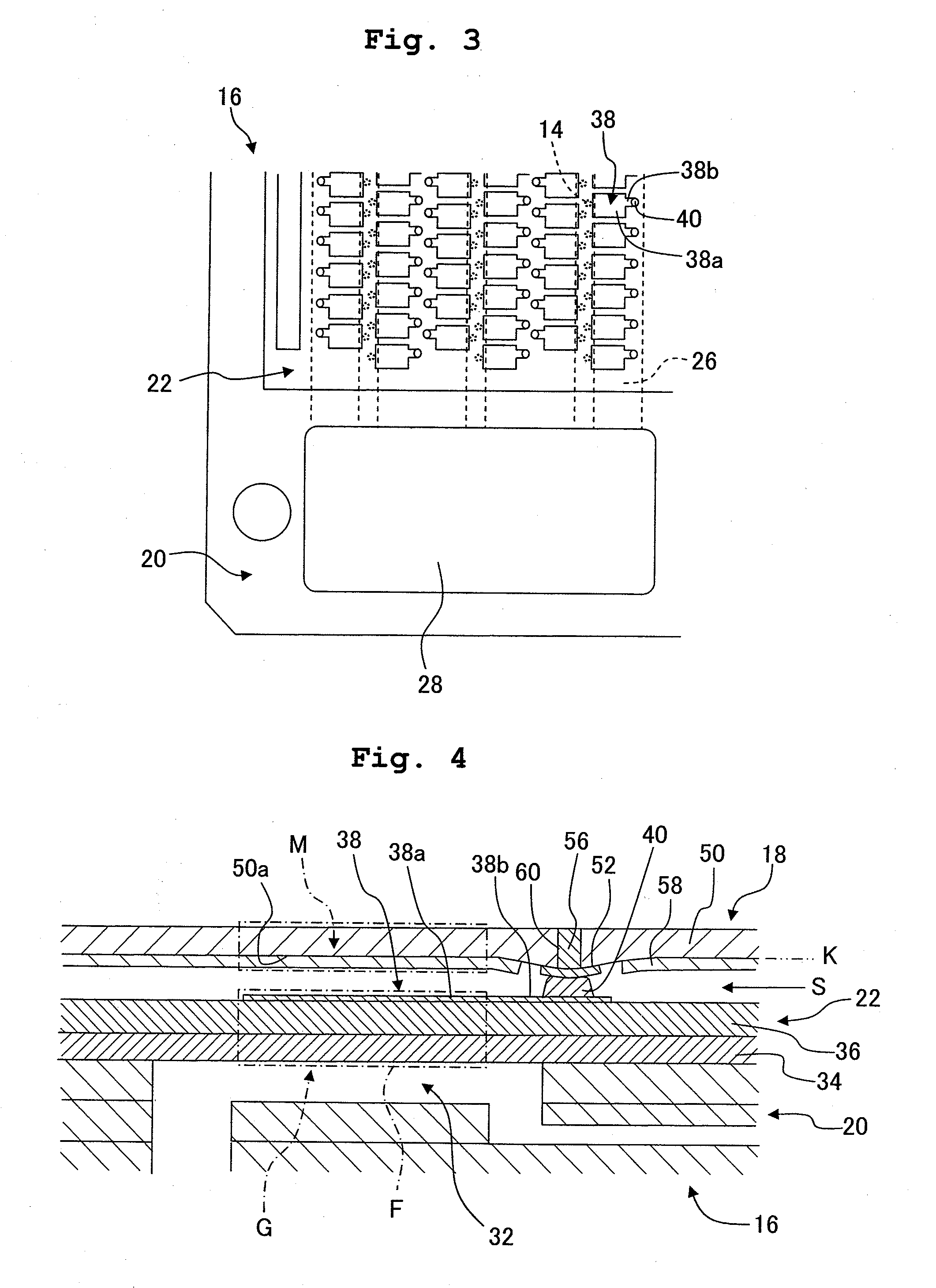
[0033]As shown in FIG. 1, an ink discharge apparatus 10 selectively discharges four color inks of black (BK), yellow (Y), cyan (C), and magenta (M) from a plurality of nozzles 14 (FIG. 2) toward a discharge objective such as the printing paper or the like (not shown) on the basis of the driving signal outputted from two driver IC's 12. In this arrangement, the ink discharge apparatus 10 principally includes an ink discharge head 16 which is provided as the “liquid discharge head”, terminals 40, and a wiring board 18.

[0034]As shown in FIG. 2, the ink discharge head 16 includes a channel unit 20 and an actuator unit 22. The channel unit 20 is constructed by staking five plates 24a to 24e. The plates 24a to 24e are stacked so that “recesses” or “through-holes”, which are formed for the plates 24a to 24e, are communicated with each other. Accordingly, four ink channels N1 to N4 (FIG. 1) are constructed corresponding to the ink colors. As shown in FIG. 2, each of the ink channels N1 to N...

second embodiment

[0050]In an ink discharge apparatus according to a second embodiment, the lands 52 of the wiring board 18 of the ink discharge apparatus 10 according to the first embodiment are changed to lands 70 as shown in FIG. 7. Other portions of the ink discharge apparatus according to the second embodiment are constructed in the same manner as those of the ink discharge apparatus 10. In other words, the lands 52 concerning the first embodiment are formed to be simply circular. On the contrary, the lands 70 concerning the second embodiment are circular, in addition to which lattice-shaped grooves 70a are formed. Therefore, according to the ink discharge apparatus concerning the second embodiment, the lands 70 can be easily deformed, because the grooves 70a are formed on the lands 70. The lands 70 can be easily extruded toward the ink discharge head 16 as compared with the surroundings thereof, and it is possible to avoid any breakage of the lands 70 at any undesired position. Further, the the...

third embodiment

[0052]In an ink discharge apparatus 80 according to a third embodiment as shown in FIG. 8, the through-holes 60, which are formed as the “hollow portions” of the ink discharge apparatus 10 according to the first embodiment, are changed to bottomed holes (bottom-equipped holes) 82. Other portions of the ink discharge apparatus 80 according to the third embodiment are constructed in the same manner as those of the ink discharge apparatus 10. The bottomed hole 82 has an opening 82a disposed on the side of the land 52 in relation to the base board 50, and the bottomed hole 82 has a bottom 82b disposed on the opposite side. The thermally expandable member 56 is provided in the bottomed hole 82.

[0053]The shape or contour of the “hollow portion” is not specifically limited provided that the thermally expandable member 56 can be provided therein. Although not shown, it is also allowable to adopt a “bottomed hole” which has a bottom formed in the base board 50 on the side of the land 52 and ...


PUM

PropertyMeasurementUnit
diameteraaaaaaaaaa
diameteraaaaaaaaaa
lengthaaaaaaaaaa

Abstract

A method for producing a liquid discharge apparatus is provided, including preparing a liquid discharge head including driving sections which apply a discharge pressure to a liquid; preparing a wiring board including a base board having lands formed on a surface and thermally expandable members arranged in hollow portions of the base board; forming terminals on electrodes of the liquid discharge head; making the lands be in contact with the terminals while securing a space between the liquid discharge head and the wiring board; making a heater to abut against areas of the wiring board arranged with the thermally expandable members; and heating the thermally expandable members by the heater so that the thermally expandable members are expanded to be brought in contact under pressure with the terminals.

Description

CROSS REFERENCE TO RELATED APPLICATION[0001]The present application claims priority from Japanese Patent Application No. 2009-227890, filed on Sep. 30, 2009, the disclosure of which is incorporated herein by reference in its entirety.BACKGROUND OF THE INVENTION[0002]1. Field of the Invention[0003]The present invention relates to a liquid discharge apparatus provided with a liquid discharge head which has a driving section to be driven so that the discharge pressure is applied to a liquid in order to discharge the liquid from a nozzle and a wiring board which is connected to the liquid discharge head, and a method for producing the same.[0004]2. Description of the Related Art[0005]For example, an ink discharge apparatus such as an ink jet printer is known as the liquid discharge apparatus provided with the liquid discharge head. A certain ink discharge apparatus is provided with an ink-jet head which has nozzles and driving sections for discharging an ink from the nozzles, and a flex...

Claims


Application Information

Patent Timeline
Patent Type & Authority Applications(United States)
IPC IPC(8): B05B7/16H01R43/00
CPCB41J2/14233B41J2/161Y10T29/49117B41J2002/14459B41J2002/14491B41J2/1623
Inventor NISHIKAWA, TATSUYA
Owner BROTHER KOGYO KK
Why Eureka
Try Eureka