Structurally designed aerodynamic riblets

a technology of aerodynamic ribs and riblets, which is applied in the direction of air-flow influencers, mechanical devices, transportation and packaging, etc., can solve the problems of reducing the performance of the riblet, degrading the appearance of the surface, and the need to replace or remove the riblet, etc., and achieves the effect of high modulus

Active Publication Date: 2011-03-31
THE BOEING CO
View PDF4 Cites 52 Cited by
  • Summary
  • Abstract
  • Description
  • Claims
  • Application Information

AI Technical Summary

Benefits of technology

[0009]In certain instances, the surface layer and riblet tips are formed from a high elongation elastomer such as epoxy, urethane, perfluoroether or fluorosilicone and the embodiments may include an adhesive layer deposited on the surface layer opposite the tips, a cladding on the riblet tips such as a UV reflective coating or a polymer support layer deposited on the surface layer opposite the tips. In other instance, the riblet tips are formed from high modulus materials selected from the set of nickel, chromium, metal alloys, glasses, ceramics, silicon carbide or silicon nitride. The tips may also be constructed of multiple materials including multilayers of high modulus and polymers. A metallic layer or discontinuous metal layer and a polymer support layer intermediate the elastomeric layer and the adhesive layer may be included as an appliqué for lightning strike or other functional application.

Problems solved by technology

However in service use such as on an aircraft aerodynamic surface, these polymer riblets are relatively easily damaged thus reducing the performance of the riblet and degrading the appearance of the surface.
These surfaces were readily gouged by tools, edges of boots, maintenance equipment impacting or rubbing along the surface resulting in the need to replace or remove the riblets.
This lack of durability has been the key impediment to the use of riblets for drag reduction.
Non-elastomeric polymeric riblets may readily fracture or permanently deform hundreds of percent with tool- or fingernail-induced pressure.
Thermoplastic polymers (fluoropolymers such as the ter-polymer tetrafluoroethylene hexafluorpropylene vinylidene fluoride (THV), fluorinated ethylene propylene (FEP) or polyethylene for example can undergo large deformations (hundreds of percent elongation) without breaking but those deformations will be largely unrecoverable destroying the both the appearance and the drag reduction benefits of the riblet structure.
Such structures may be undesirable in normal service use on an aircraft or other vehicle.

Method used


Image

  • Structurally designed aerodynamic riblets
  • Structurally designed aerodynamic riblets
  • Structurally designed aerodynamic riblets

Examples


Embodiment Construction

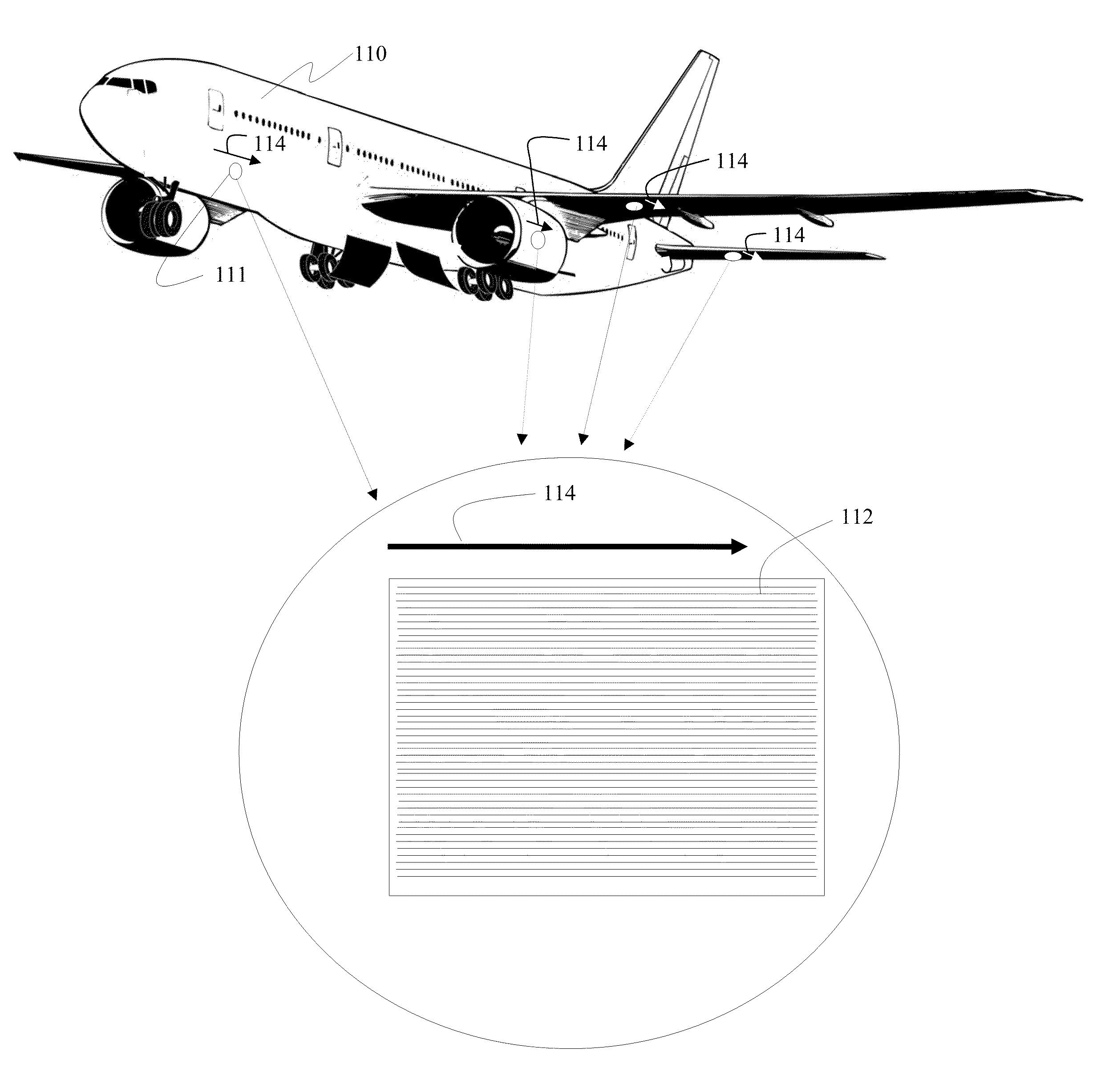
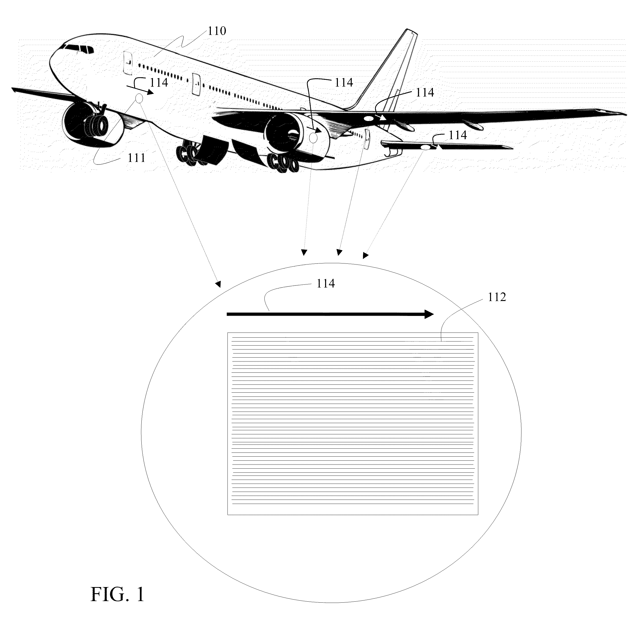
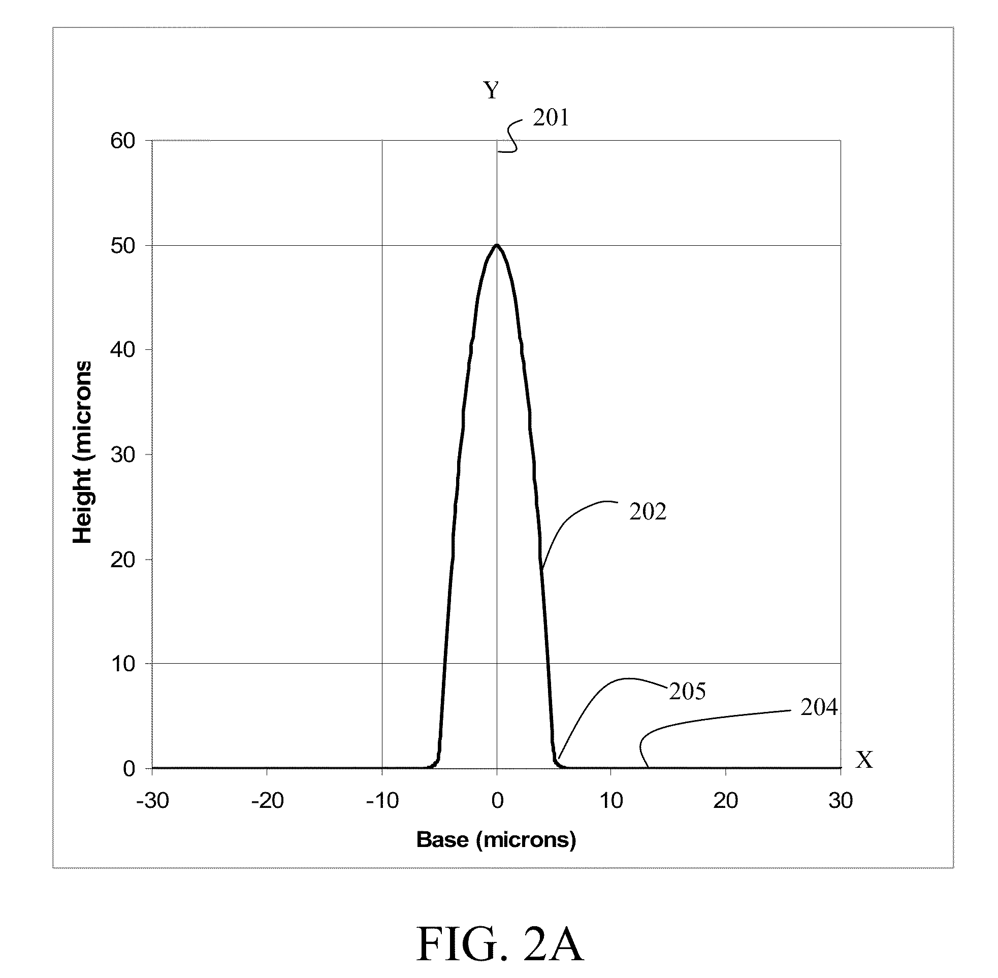
[0035]The embodiments disclosed herein provide riblets structurally designed for maximum durability by providing equalized stress along the riblet surface. The embodiments disclosed herein provide a parabolic section and are particularly applicable for high modulus materials and high elongation elastomeric materials for riblets that may be impacted by ground support equipment or environmental hazards such as hail to avoid permanent deformation / damage. These embodiments also allow an optimized structural design of riblets providing the capability for them to be thinner and more aerodynamically efficient. Materials having a small elastic region which would normally be plastically deformed in a non-recoverable manner may more readily be employed with the parabolic section defined herein. An exemplary embodiment of elastomeric riblets having a structure as will be described in greater detail subsequently is shown as a portion of an aerodynamic surface for an aircraft as shown in FIG. 1....


PUM

PropertyMeasurementUnit
elongationaaaaaaaaaa
section stress plotaaaaaaaaaa
heightaaaaaaaaaa

Abstract

An array of aerodynamic riblets is formed with a surface layer for adhering to an aerodynamic surface and a plurality of riblet tips having a parabolic cross section extending from the surface layer.

Description

REFERENCE TO RELATED APPLICATIONS[0001]This application is copending with U.S. patent application Ser. No. 12 / 361,882 entitled Shape Memory Riblets by inventors Diane C. Rawlings and Terry L. Schneider having attorney docket no. 08-0936 and U.S. patent application Ser. No. 12 / 361,918 entitled Amorphous Metal Riblets by inventors Diane C. Rawlings and Stephen Christensen having attorney docket no. 08-0944 both filed on Jan. 29, 2009 the disclosures of which are incorporated herein by reference. This application is also copending with U.S. patent application Ser. No. ______ filed substantially concurrently herewith entitled Elastomeric Riblets by inventors Diane C. Rawlings and Alan Burg having attorney docket no. 09-0153 the disclosure of which is incorporated herein by reference.BACKGROUND INFORMATION[0002]1. Field[0003]Embodiments of the disclosure relate generally to the field of tailoring of surface geometries for aerodynamic improvements to aircraft or surfaces having a flow int...

Claims


Application Information

Patent Timeline
Patent Type & Authority Applications(United States)
IPC IPC(8): B64C1/38B29C33/42
CPCB64C21/10F15D1/12Y10T156/1039B29C65/4855B64C2230/26Y02T50/166Y02T50/10
Inventor RAWLINGS, DIANE C.MCLEAN, JR., JAMES D.MATHEWS, MARY J.
Owner THE BOEING CO
Why Eureka
Try Eureka