Light-Emitting Diode Illumination Apparatuses

Inactive Publication Date: 2011-03-31
SHEN YU NUNG +1
View PDF1 Cites 128 Cited by
  • Summary
  • Abstract
  • Description
  • Claims
  • Application Information

AI Technical Summary

Benefits of technology

[0007]Accordingly, an object of the invention is to provide light-emitting diode illumination appara

Problems solved by technology

However, most of the LEDs lamps today are retailed to dissipate heat through heat-dissipating fins and/or cooling fans and heat-conductive pastes.
The designs of these types result in coincidence of the light path and the heat transfer path and lead to a phenomenon known as radiative heat transfer.
The traditional

Method used


Image

  • Light-Emitting Diode Illumination Apparatuses
  • Light-Emitting Diode Illumination Apparatuses
  • Light-Emitting Diode Illumination Apparatuses

Examples


Embodiment Construction

[0075]Before the present invention is described in greater detail, it should be noted that the same or like elements are denoted by the same reference numerals throughout the disclosure. Moreover, the elements shown in the drawings are not illustrated in actual scale, but are expressly illustrated to explain in an intuitive manner the technical feature of the invention disclosed herein.

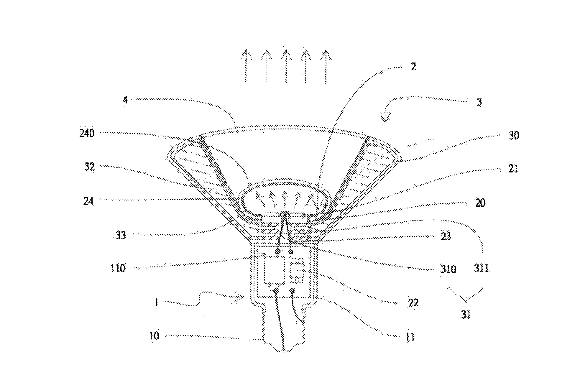
[0076]FIG. 1 is a schematic, cross-sectional view of the light-emitting diode illumination apparatus according to the first preferred embodiment of the invention.

[0077]The LED illumination apparatus shown in FIG. 1 comprises a body 1, a light source module 2 and a heat-dissipating module 3.

[0078]According to this embodiment, the body 1 has a lower portion 10 configured in the form of a standard E27-type threaded adapter and an upper portion 11 provided with a power source module accommodating chamber 110.

[0079]The heat-dissipating module 3 includes a funnel-shaped hollow case 30 disposed at a top end ...


PUM


Abstract

The present invention relates to an LED illumination apparatus. The apparatus includes a body having a lower portion adapted for coupling to a power socket and an upper portion provided with a power source module accommodating chamber. A heat-dissipating module includes a funnel-shaped hollow case disposed at a top end of the upper portion and filled with a coolant fluid, wherein the hollow case has a small diameter open end adjacent to the body and a large diameter open end remote from the body. A light source module includes amounting substrate disposed at the small diameter open end, an LED mounted on the mounting substrate, and a power source module disposed within the power source module accommodating chamber in a manner electrically connected to and supplying working power to the LED.

Description

BACKGROUND OF THE INVENTION[0001]1. Field of the Invention[0002]The present invention relates to light-emitting diode illumination apparatuses.[0003]2. Description of the Prior Art[0004]As light-emitting diodes (LEDs) are increasingly improved in terms of output power, the waste heat generated thereby is increased proportionally and the dissipation of waste heat becomes much important for high-power LEDs. However, most of the LEDs lamps today are retailed to dissipate heat through heat-dissipating fins and / or cooling fans and heat-conductive pastes. The designs of these types result in coincidence of the light path and the heat transfer path and lead to a phenomenon known as radiative heat transfer. The traditional designs possess a deficiency in dissipation of waste heat, causing serious luminous decay of LEDs and reducing the lifespan of LEDs. All of these factors result in an increased manufacture cost, which is one of the major reasons that the extensive use of LEDs in illuminat...

Claims


Application Information

Patent Timeline
IPC IPC(8): H01J61/52
CPCF21K9/135F21V29/83F21K9/17F21K9/52F21K9/56F21V3/00F21V23/023F21V29/004F21V29/006F21W2131/103F21Y2101/02F21Y2111/005F21S8/086F21V29/505F21V29/506F21V29/58F21V29/767F21K9/137F21K9/232F21K9/233F21K9/61F21K9/64F21Y2115/10F21Y2107/30F21Y2107/90F21K9/275F21V29/51
Inventor SHEN, YU-NUNGWANG, TSUNG-CHI
Owner SHEN YU NUNG
Why Eureka
Try Eureka