Method and Device for Adjusting Brightness of an Optical Touch Panel

a technology of optical touch panel and brightness adjustment, which is applied in the direction of instruments, light sources, computing, etc., can solve the problems of unsuitable fixed brightness level, waste of energy, and waste of energy

Inactive Publication Date: 2011-03-31
TOSHIBA GLOBAL COMMERCE SOLUTIONS HLDG
View PDF19 Cites 43 Cited by
  • Summary
  • Abstract
  • Description
  • Claims
  • Application Information

AI Technical Summary

Benefits of technology

[0015]In accordance with a second aspect of the various embodiments, an optical touch panel device is provided for adjusting brightness of an optical touch panel. The optical touch panel device may comprise a display module having a display area and a back light source, control circuitry electrically coupled to the display module, and an optical position detection device coupled to the display module. The optical position detection device may comprise optical transmitting devices and optical receiving devices. The optical receiving devices may detect a current ambient light level on the display module, and may generate a current ambient light level signal indicative of the current ambient light level, and may transmit the currently ambient light level signal to the control circuitry. The control circuitry may adjust brightness of the back light source based on the current ambient light level signal.
[0016]The back light source may be in one of a plurality of operation modes in response to the one of the conditions of the ambient lighting. The operation modes may include a low brightness mode, a power saving mode, and a normal mode similar to the corresponding operation modes described above with respect to the first aspect of the various embodiments.
[0017]The control circuitry may further comprise a microprocessor and a memory. The optical touch panel device may further comprise an amplifier electrically coupled between the optical receiving devices and the microprocessor for amplifying the current ambient light level signal generated by the optical receiving devices. The amplifier may have a gain inversely proportional to the current ambient light level, and the current ambient light level may be proportional to the brightness of the back light source.
[0018]The memory of the control circuitry may comprise a current gain calculation module for obtaining a current gain G under a user-adjusted normal ambient light condition after the optical receiving devices are exposed for a first period of time, a minimum gain calculation module for obtaining a minimum gain Gmin under a maximum ambient light condition after the optical receiving devices are exposed for a second period of time, and a maximum gain calculation module for obtaining a maximum gain Gmax under a minimum ambient light condition after the optical receiving devices are exposed for a third period of time. The memory may further comprise an automatic calibration calculation module for automatically calibrating the back light source to an automatically calibrated brightness based on the current ambient light level and a predefined relation between the current ambient light level and the brightness of the back light source. Accordingly, the plurality of operation modes may comprise an automatic calibration mode in which the back light source is automatically adjusted to the automatically calibrated brightness by the automatic calibration calculation module in response to a change in the current ambient light level

Problems solved by technology

However, in many situations in which devices use optical touch panels, a fixed brightness level may not be suitable.
For example, energy may be wasted if devices such as POS systems, ATMs, kiosks, etc. are turned on at a fixed brightness level for a long period of time.
In addition, some shops with alternate business hours may have lighting needs that change frequently, and thus energy may be wasted if the devices are turned on at a fixed brightness level for a long period of time.
Moreover, energy may be wasted if the devices are turned on during non-business hours.
Furthermore, leaving optical touch panels turned on unnecessarily will also shorten the life thereof, especially if the brightness level is high.
Taking a POS system for example, in different locations (such as the extremes of a high-latitude location and a low-latitude location and in-between locations) or during different periods of time (such as the extremes of night and day and in-between periods), a fixed brightness level is not a good solution.
However, such solution is usually considered troublesome, and a user tends to set the brightness to the maximum value, which may shorten the lifespan of the optical touch panel.
However, such solution may increase manufacturing cost.
In addition, the light sensor used in such solution (e.g., a CDS sensor) may have relatively unacceptable errors.
Furthermore, the additional light sensor needed for such solution must be mounted on the optical touch panel, thus increasing assembly overhead.

Method used


Image

  • Method and Device for Adjusting Brightness of an Optical Touch Panel
  • Method and Device for Adjusting Brightness of an Optical Touch Panel
  • Method and Device for Adjusting Brightness of an Optical Touch Panel

Examples


Embodiment Construction

[0032]Reference throughout this specification to “one embodiment,”“an embodiment,” or similar language signifies that a particular feature, structure, or characteristic described in connection with the embodiment is included in at least one embodiment. Thus, appearances of the phrases “in one embodiment,”“in an embodiment,” and similar language throughout this specification may, but do not necessarily, refer to the same embodiment.

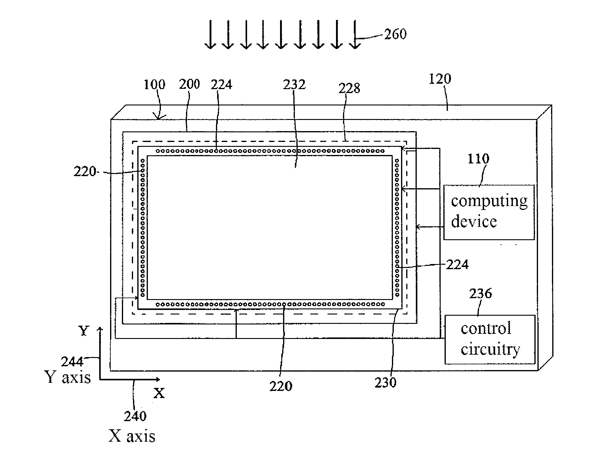
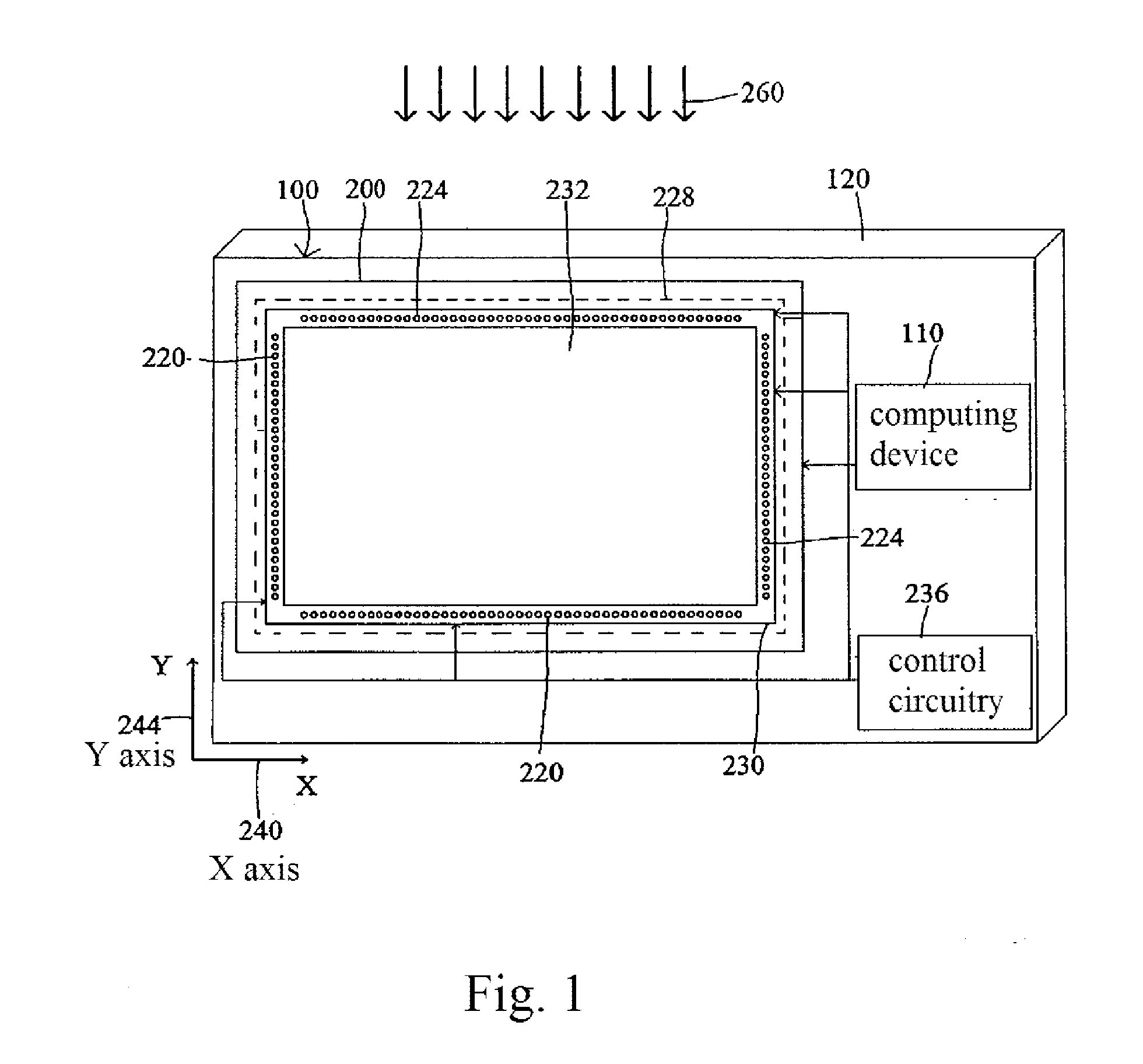
[0033]FIG. 1 illustrates an electrical device 100 (e.g., a Point of Sale (POS) device) having an optical touch screen apparatus 200 (e.g., an infrared touch screen apparatus) according to an exemplary embodiment. The electrical device 100 may also comprise a computing device 110 and a device housing 120. The optical touch screen apparatus 200 may comprise a display module (e.g., a LCD display module) 228 and a frame (e.g., an infrared frame) 230 arranged over the display module 228. Both the display module 228 and the frame 230 may be of rectangular shape....


PUM


Abstract

A method and device are provided for adjusting brightness of an optical touch panel. The optical touch panel comprises a microprocessor, a display module including a back light source, and an optical position detection device including optical transmitting devices and optical receiving devices. The method comprises detecting, via the optical receiving devices, a current ambient light level on the display module. The method further comprises generating, via the optical receiving devices, a current ambient light level signal indicative of the current ambient light level and transmitting the current ambient light level signal to the microprocessor. Furthermore, the method comprises adjusting, via the microprocessor, brightness of the back light source based on the current ambient light level signal.

Description

RELATED APPLICATION[0001]This application claims priority under 35 U.S.C. §119 to Taiwanese Patent Application No. 98133301 filed Sep. 30, 2009, the entire text of which is specifically incorporated by reference herein.FIELD OF THE INVENTION[0002]The various embodiments described herein relate to an information display apparatus, and more particularly to an optical touch screen apparatus.BACKGROUND OF THE INVENTION[0003]Touch panels are used for input and output interfaces of information apparatuses, e.g., Point of Sale (POS) systems, mobile devices, automatic teller machines (ATMs), cashers, kiosks, and interactive multimedia stations. Touch panels are typically categorized as pressure-sensitive touch panels, resistance type touch panels, surface sound wave type touch panels, capacitance touch panels, and infrared touch panels.[0004]For optical touch panels such as infrared touch panels, a plurality of infrared transmitting devices and a plurality of infrared receiving devices are ...

Claims


Application Information

Patent Timeline
Patent Type & Authority Applications(United States)
IPC IPC(8): G06F3/041
CPCG06F3/0416G06F3/0421G09G2320/0626G09G2360/144H05B37/0218G09G3/3406G09G2320/0633G06F3/0412Y02B20/40H05B47/11
Inventor HSIEH, TSUNG HSUANHSUAN, WEI YILEE, YI SHENGPARSONS, ROBERT DAVIDYANG, CHIA LIN
Owner TOSHIBA GLOBAL COMMERCE SOLUTIONS HLDG
Why Eureka
Try Eureka