Scan-type display device control circuit

a display device and control circuit technology, applied in static indicating devices, instruments, cathode-ray tube indicators, etc., can solve the problem of more difficulty in flickering of led display devices, achieve the effect of reducing the width of inputting data, preventing a great mass of data, and efficiently enhancing the refresh ra

Active Publication Date: 2011-03-31
MACROBLOCK INC
View PDF3 Cites 22 Cited by
  • Summary
  • Abstract
  • Description
  • Claims
  • Application Information

AI Technical Summary

Benefits of technology

[0019]The scan-type display device control circuit can utilize frame data circularly and repeatedly, so as to prevent a great mass of data from being transmitted repeatedly. Therefore, a band width for inputting data can be reduced significantly. Furthermore, the scrambled PMW signal generating device can scramble a PMW signal with a long period into a plurality of scrambled PMW signals with a short period. Therefore, the refresh rate can be efficiently enhanced without changing the band width for inputting data.

Problems solved by technology

The higher the refresh rate is, the more difficulty the LED display device flickers (for example, when taking a photo by using a high-speed shutter of a photography appliance).

Method used


Image

  • Scan-type display device control circuit
  • Scan-type display device control circuit
  • Scan-type display device control circuit

Examples


first embodiment

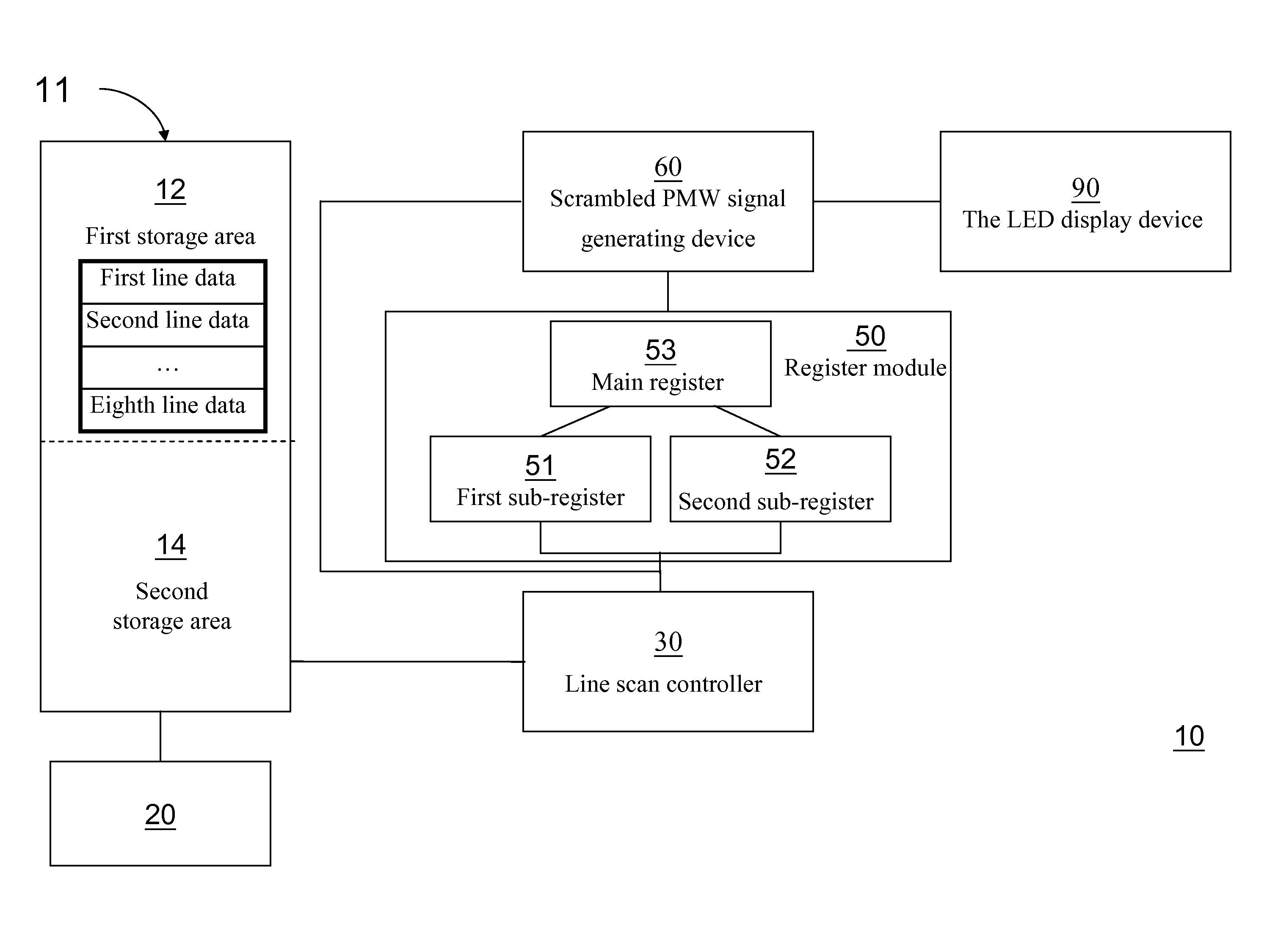
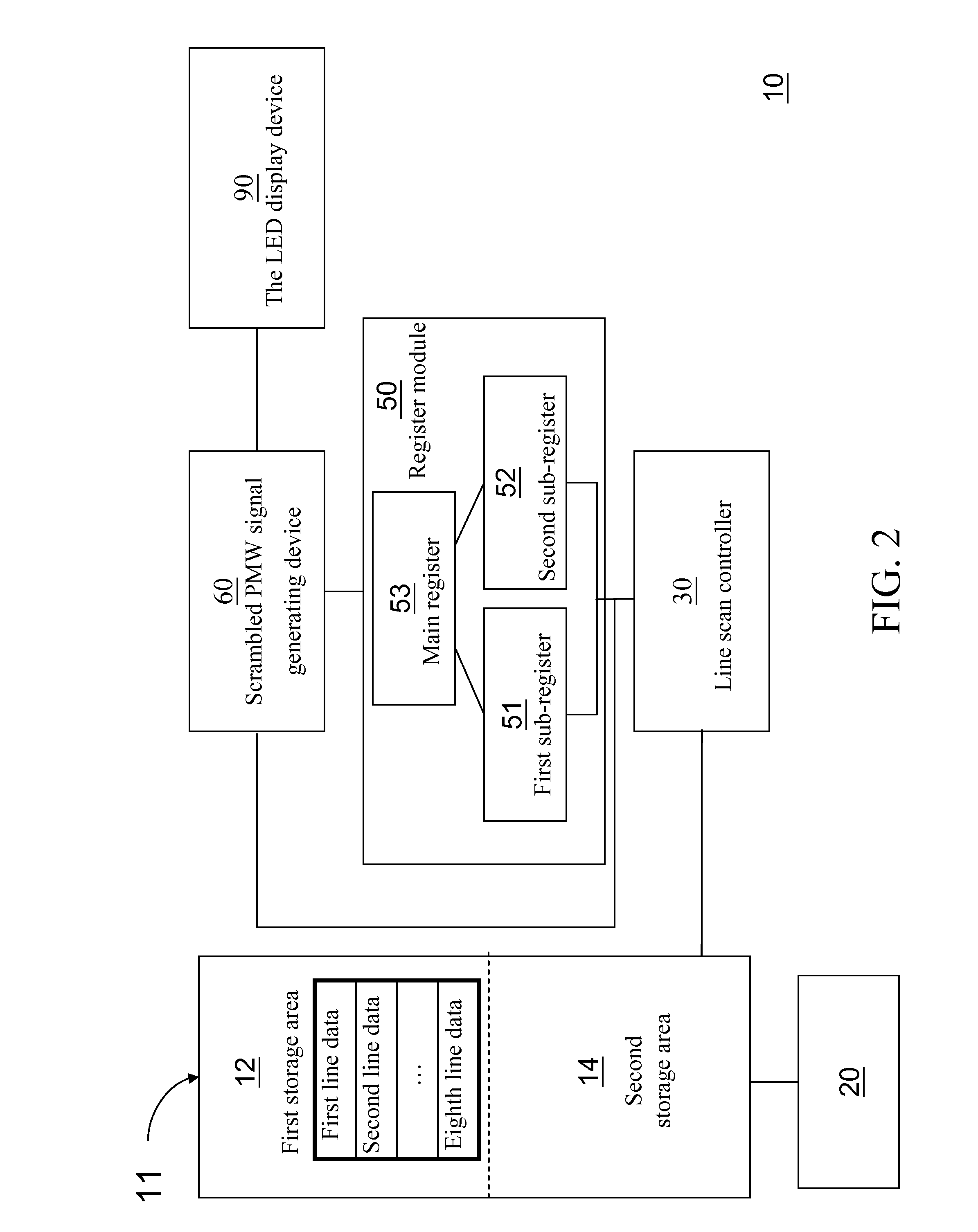
[0031]Referring FIG. 2, a block diagram of a system according to the present invention is shown. The scan-type display device control circuit 10 comprises a ping-pong buffer 11, a data storage controller 20, a line scan controller 30, a display buffer 50, and a scrambled PMW signal generating device 60.

[0032]The ping-pong buffer 11 comprises a first storage area 12 and a second storage area 14. The ping-pong buffer 11 can write in and read data continuously. The data storage controller 20 is used to receive the frame data in sequence, and store the data in the first storage area 12 or the second storage area 14 alternately.

[0033]The line scan controller 30, logically connected to the ping-pong buffer 11, is used to capture line data in the frame data from the first storage area 12 or the second storage area 14 alternately.

[0034]The display buffer 50, logically connected to the line scan controller 30, is used to temporarily store the line data in the frame data in the first storage ...

second embodiment

[0056]FIG. 4B is block diagram of a system in the scrambled PMW signal generating device 60. The scrambled PMW signal generating device 60 comprises a random number generator 43 and a first comparator 61. The random number generator 43 generates a random number signal. The first comparator 61 comprises a first input end and a second input end. The first input end is used to input the line data, and the second input end is used to input a random number signal. When the value of the first input end is larger than that of the second input end, the first comparator 61 outputs a first signal, and when the value of the first input end is equal to or smaller than that of the second input end, the first comparator outputs a second signal. For example, the first signal is a “logic 1” signal, and the second signal is a “logic 0” signal. Only when the “logic 1” signal is transmitted to the LED, i.e., the value of the line data is larger than random number signal generated by the random number ...


PUM


Abstract

A scan-type display device control circuit is suitable for receiving successive frame data and driving a light-emitting diode (LED) display device accordingly. The scan-type display device control circuit includes a ping-pong buffer, a data storage controller, a line scan controller, a display buffer, and a scrambled pulse width modulation (PMW) signal generating device. The scan-type display device control circuit can utilize frame data circularly and repeatedly, so as to prevent a great mass of data from being transmitted repeatedly. Therefore, a band width for inputting data can be reduced significantly. Furthermore, the scrambled PMW signal generating device can scramble a PMW signal with a long period into a plurality of scrambled PMW signals with a short period. Therefore, the refresh rate can be efficiently enhanced without changing the band width for inputting data.

Description

CROSS-REFERENCE TO RELATED APPLICATIONS[0001]This non-provisional application claims priority under 35 U.S.C. §119(a) on Patent Application No(s). 098133304 filed in Taiwan, R.O.C. on Sep. 30, 2009, the entire contents of which are hereby incorporated by reference.BACKGROUND[0002]1. Field of Invention[0003]The present invention relates to a circuit, and more particularly to a scan-type display device control circuit.[0004]2. Related Art[0005]In recent years, the cost of manufacturing light-emitting diodes (LEDs) is greatly reduced. Therefore, LED displays have been widely applied in various occasions, such as gymnasiums and billboards.[0006]Usually, an LED display device uses thousands of LEDs as displaying pixels. A frame may be constituted by pixels having different brightness, and multiple frames may be displayed in sequence to constitute a dynamic image.[0007]The pixels are controlled by a controller respectively. According to input data, the controller transmits an ON signal or...

Claims


Application Information

Patent Timeline
Patent Type & Authority Applications(United States)
IPC IPC(8): G09G5/39
CPCG09G3/2018G09G3/2025G09G3/2044G09G3/2096G09G2360/18G09G3/3275G09G2310/027G09G2320/0247G09G3/3216Y02B20/30
Inventor WU, KEN TANGSHIH, FU YANG
Owner MACROBLOCK INC
Why Eureka
Try Eureka