
Electro-optic bragg deflector and method of using it as laser q-switch in an actively q-switched laser and an actively q-switched wavelength-conversion laser

Active Publication Date: 2011-03-31
NATIONAL TSING HUA UNIVERSITY
View PDF4 Cites 13 Cited by
  • Summary
  • Abstract
  • Description
  • Claims
  • Application Information

AI Technical Summary

Benefits of technology

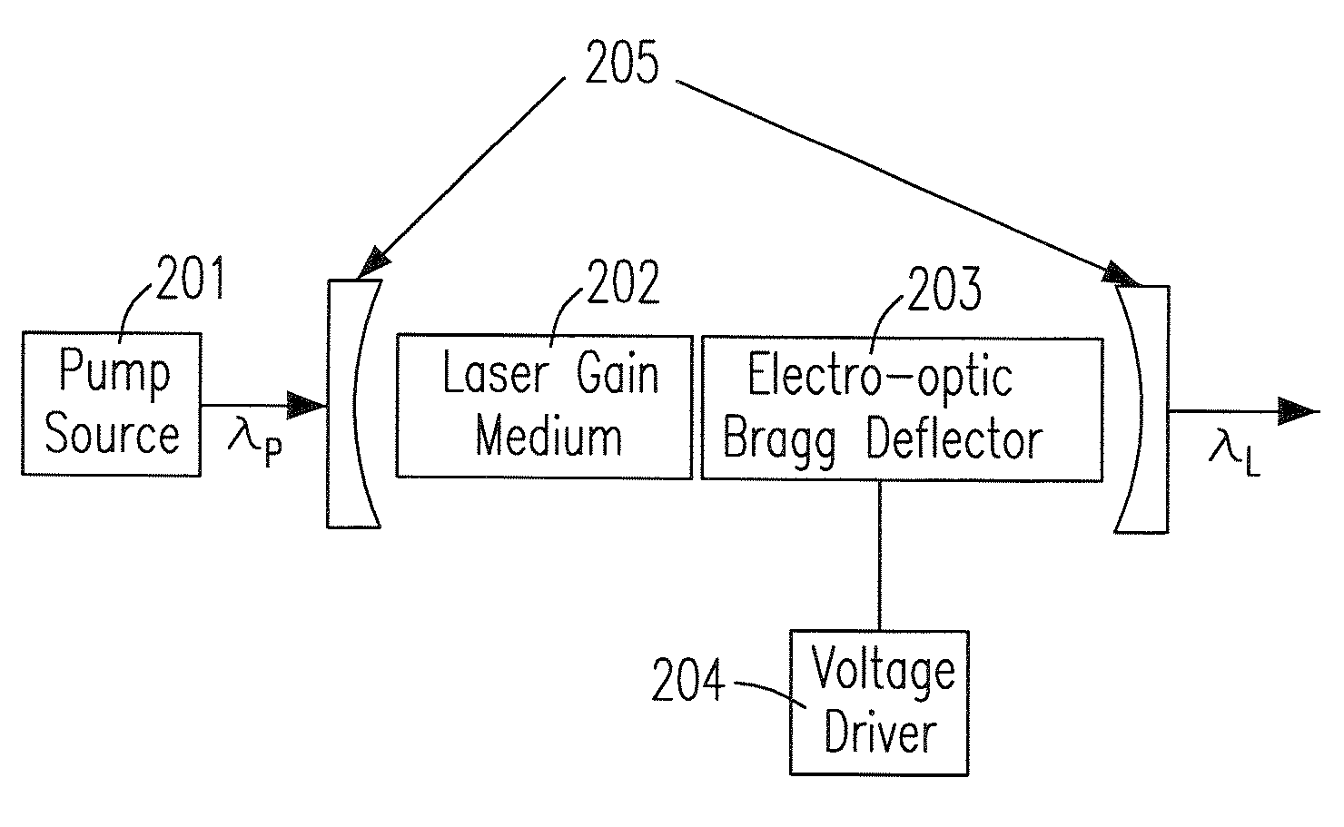
[0008]It is a primary objective of the present invention to provide an EO Bragg deflector. It is a further objective of the present invention to provide an improved actively Q-switched laser system which adopts the EO Bragg deflector as a laser Q-switch. It is an additional objective of the present invention to provide a Q-switched wavelength-conversion laser source that is more compact and efficient for producing coherent laser radiations by integrating a wavelength converter, in particular a QPM wavelength converter, to the EO Bragg deflector in the Q-switched laser system.
[0011]According to a third preferred embodiment, the apparatus in general comprises a pump source, a laser gain medium, an EO Bragg deflector, a voltage driver, a laser cavity, and a laser wavelength converter. In this embodiment, the laser wavelength converter is added to the second embodiment to convert the wavelength of the Q-switched laser to a different one. Taking the χ(2)-based wavelength converter as an example, this wavelength converter can be a second harmonic generator (SHG), optical parametric generator (OPG), optical parametric oscillator (OPO), sum frequency generator (SFG), difference frequency generator (DFG), or a combination of them. Since both the EO Bragg deflector and the χ(2) laser-wavelength converter utilize the second-order susceptibility, they can be monolithically integrated in a single crystal substrate of a nonlinear-optical material. In particular, the fabrication process of an EO Bragg deflector can be fully compatible with that of a QPM wavelength converter. Integrating the two in a monolithic nonlinear-crystal substrate is straightforward.

Problems solved by technology

For instance, a diode laser is a popular laser source because of its small size, low-power consumption, and ease of mass production; however, the emission wavelength of a diode laser is limited by material properties or, more specifically, by the quantum energy levels of the laser gain medium.
Since the laser wavelength is fixed to the available energy levels of a laser material, the wavelength of a DPSS laser employing a certain laser gain medium can not be arbitrarily tuned.
Such a stringent phase-matching requirement usually sacrifices the largest available nonlinear coupling coefficient in a given nonlinear optical material and limits the energy conversion efficiency of laser wavelength conversion.

Method used


Image

  • Electro-optic bragg deflector and method of using it as laser q-switch in an actively q-switched laser and an actively q-switched wavelength-conversion laser
  • Electro-optic bragg deflector and method of using it as laser q-switch in an actively q-switched laser and an actively q-switched wavelength-conversion laser
  • Electro-optic bragg deflector and method of using it as laser q-switch in an actively q-switched laser and an actively q-switched wavelength-conversion laser

Examples


experimental examples

OF THE INVENTION

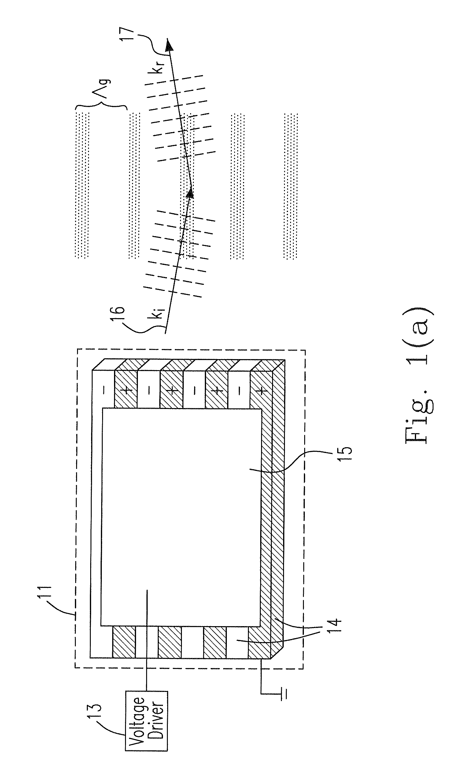
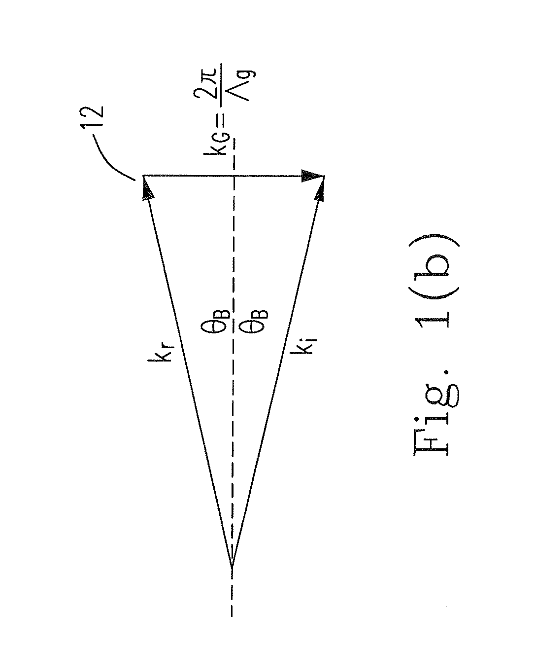
[0030]According to the first preferred embodiment of the present invention, we fabricated a 1.42-cm-long, 1-cm-wide, and 780-μm-thick PPLN crystal as an EO Bragg deflector. The grating period of the EO PPLN Bragg deflector was 20.13 μm, corresponding to a Bragg angle of 0.7° for the first-order diffraction beam at 1064 nm. The ±z surfaces of the PPLN crystal were coated with 500-nm thick NiCr electrodes and the ±y surfaces were anti-reflection coated at 1064 nm We first measured the diffraction efficiency of the PPLN crystal by using a continuous-wave laser at 1064 nm with 110-μm laser radius. The incident angle of the laser was pre-aligned to the Bragg angle. FIG. 6 shows the measured transmittance of the zero-order diffraction beam versus applied voltage at 30° C. and 100° C. It is seen from the curves that the diffraction loss of this EO Bragg deflector is fairly insensitive to temperature. The slight offset of the transmittance peak from the zero voltage is due t...


PUM


Abstract

The configurations of an electro-optic Bragg deflector and the methods of using it as a laser Q-switch in a Q-switched laser and in a Q-switched wavelength-conversion laser are provided. As a first embodiment, the electro-optic Bragg deflector comprises an electrode-coated electro-optic material with one of a 1D and a 2D spatially modulated electro-optic coefficient. When a voltage is supplied to the electrodes, the electro-optic material behaves like a Bragg grating due to the electro-optically induced spatial modulation of the refractive index. The second embodiment relates to an actively Q-switched laser, wherein the electro-optic Bragg deflector functions as a laser Q-switch. The third embodiment of the present invention combines the Q-switched laser and a laser-wavelength converter to form a Q-switched wavelength-conversion laser, wherein the EO Bragg deflector can be monolithically integrated with a quasi-phase-matching wavelength converter in a fabrication process.

Description

FIELD OF THE INVENTION[0001]The present invention is a CIP application of the parent application “ELECTRO-OPTIC BRAGG DEFLECTOR AND METHOD OF USING IT AS LASER Q-SWITCH IN A Q-SWITCHED LASER AND A Q-SWITCHED WAVELENGTH-CONVERSION LASER” bearing on the Ser. No. 12 / 038,839, filed on Feb. 28, 2008, which is incorporated herein by reference as if fully set forth. The present invention relates to an electro-optic Bragg deflector. In particular, it relates to the use of the electro-optic Bragg deflector as a laser Q-switch for an actively Q-switched laser and for an actively Q-switched wavelength-conversion laser.BACKGROUND OF THE INVENTION[0002]With the rapid advancement of the laser technologies, laser sources are becoming more compact and efficient. For instance, a diode laser is a popular laser source because of its small size, low-power consumption, and ease of mass production; however, the emission wavelength of a diode laser is limited by material properties or, more specifically, ...

Claims


Application Information

Patent Timeline
IPC IPC(8): H01S3/117G02F1/295
CPCG02F1/292G02F1/3558G02F1/3775G02F2201/305H01S3/0602H01S3/1673H01S3/108H01S3/1083H01S3/109H01S3/115H01S3/09415
Inventor CHIANG, AN-CHUNGLIN, SHOU-TAIHUANG, YEN-CHIEHLIN, YEN-YINCHANG, GUEY-WU
Owner NATIONAL TSING HUA UNIVERSITY
Learn More