
Scalable matrix for the in vivo cultivation of bone and cartilage

a matrix and in vivo technology, applied in the field of in vivo regeneration, can solve the problems of large bone loss, complex grafting procedure, and bone defects that require bone grafting procedures, and achieve the effects of rapid and rapid scaling, high osteoinduction and osteoconductive, and immediate structural stability and strength

Inactive Publication Date: 2011-03-31
SIVANANTHAN SURESHAN +3
View PDF1 Cites 21 Cited by
  • Summary
  • Abstract
  • Description
  • Claims
  • Application Information

AI Technical Summary

Benefits of technology

[0020]It is an object of the present invention to provide devices (and methods) for use, in bone and tissue regeneration which provide immediate structural stability and strength, create a highly osteoinductive and osteoconductive micro-environment, can be quickly and r

Problems solved by technology

Bone loss is a major problem in trauma and orthopaedic surgery.
Injury, disease and developmental defects can all result in bone defects that require bone grafting procedures, where new bone or a replacement material is placed in apertures around a fractured bone, or in bone defects.
In the context of autograft for injuries such as bone fractures, the grafting procedure can be quite complex, and may fail to heal properly.
The drawbacks for autograft procedures include surgical complications (e.g., acute and chronic pain, inflammation, infection), and limitations in relation to the amount of bone that can be harvested for grafting.
Furthermore, complications occurring after bone grafting include fracture at the donor site after cortical graft removal, intra-operative bleeding and postoperative pain after iliac crest biopsy and stress fractures, hernias through an iliac donor site and gait problems.
However, there is a risk of disease transmission from the donor to the recipient of the bone graft material, which is not overcome by pre-implantation treatment of the tissue with techniques such as gamma irradiation.
Furthermore, the allograft may not knit well with the patient's own bone, leading to weakness at the point of union of the graft.
Also, where bone is harvested from a donor, there exist the same risks as harvesting replacement bone from the patient, as discussed above.
In the case of certain bone substitute materials, there is the disadvantage that they do not become permanently incorporated into a patient's own bone and are thus

Method used


Image

  • Scalable matrix for the in vivo cultivation of bone and cartilage
  • Scalable matrix for the in vivo cultivation of bone and cartilage
  • Scalable matrix for the in vivo cultivation of bone and cartilage

Examples


example 1

Treating Lumbar Compression or Burst Fractures

[0107]The traditional way of treating these fractures is to perform a Vertebroplasty or Kyphoplasty in the case of compression fractures and in the case of burst fractures of the spine requiring surgical intervention to achieve biomechanical stability, to perform a combined anterior instrumentation and short segment posterior instrumentation (SSPI). In low grade burst fractures, Vertebroplasty plus SSPI may provide a less invasive method of stabilising the burst fracture but there have been no conclusive tests or patient trials showing that this method is stable. Moreover there is a risk of cement or existing bone substitute materials leaking out and injuring the spinal cord, nerves or blood vessels.

[0108]It is important to note that vertebral burst fractures are typically associated with high impact axial loading resulting from trauma.

[0109]Surgical Instructions

[0110]Step One

[0111]Place the suitably consented and anaesthetised patient p...

example 2

Correction of Various Structural Defects

[0123]a. Fill the defects in the talar dome of the ankle following post traumatic osteochondral fractures where there is a large hole. Scalable matrix is filled into the curetted holes.

[0124]b. Fill the defects in surface of the knee where there are defects / holes following osteochondritis dissecans. Place the matrix into the curetted holes.

[0125]c. Fill the defects in the mid portion of the scaphoid bone where there is an established non-union with a large defect which needs filling before a screw is placed.

[0126]d. Following avascular necrosis of the femoral head there is a large cavity which could be filled with the matrix prior to placing a re-surfacing metallic femoral head.

example 3

Maxillofacial Surgery

[0127]In maxillofacial surgery augmentation procedures, the scalable matrix could be used. One particular example is sinus floor augmentation; however all bone cavities such as those from tooth extractions, cysts, fractures or defects after tumour removal can be filled using the scalable matrix.


PUM

PropertyMeasurementUnit
Volumeaaaaaaaaaa
Shapeaaaaaaaaaa
Dimensionaaaaaaaaaa

Abstract

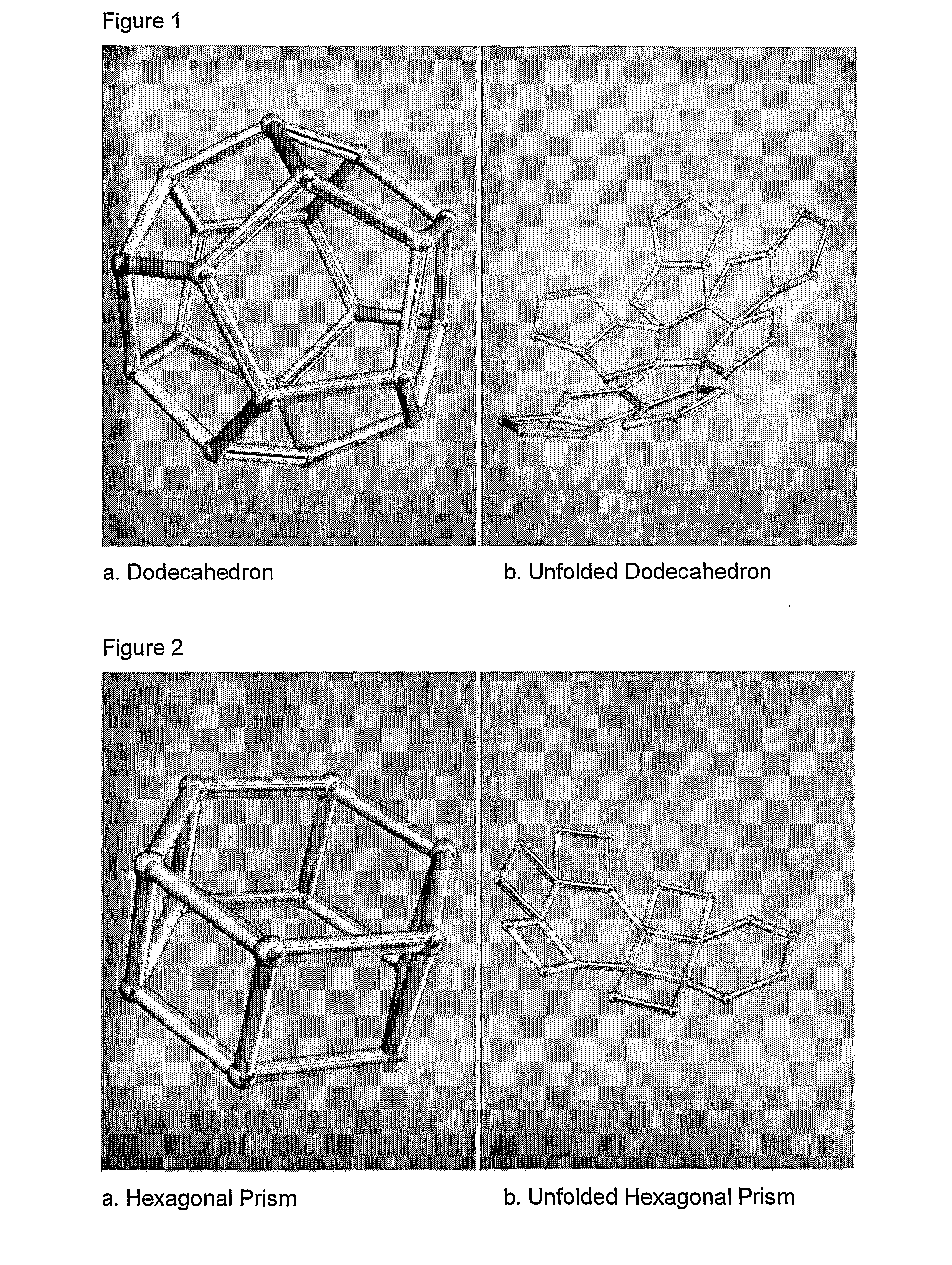
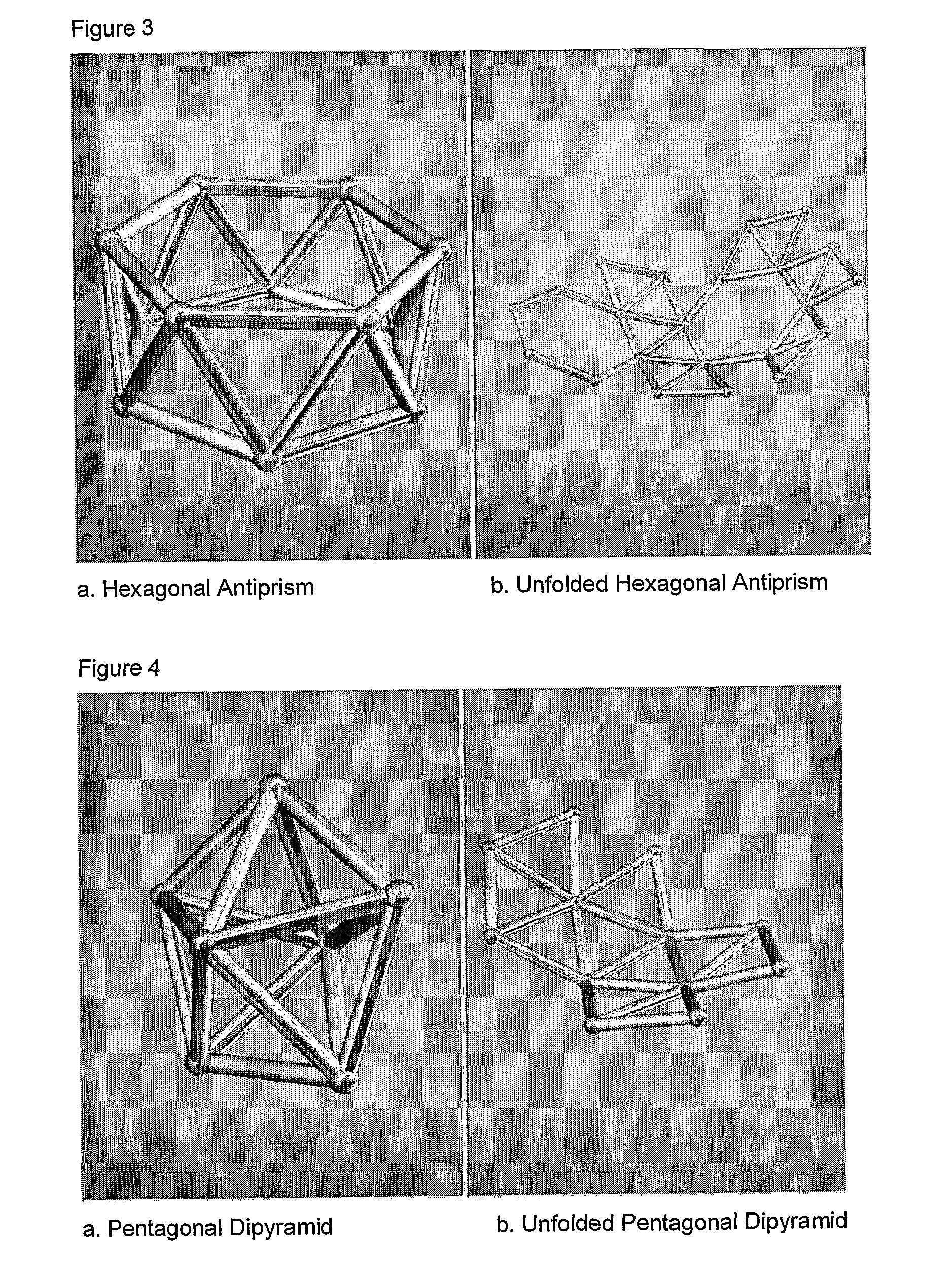
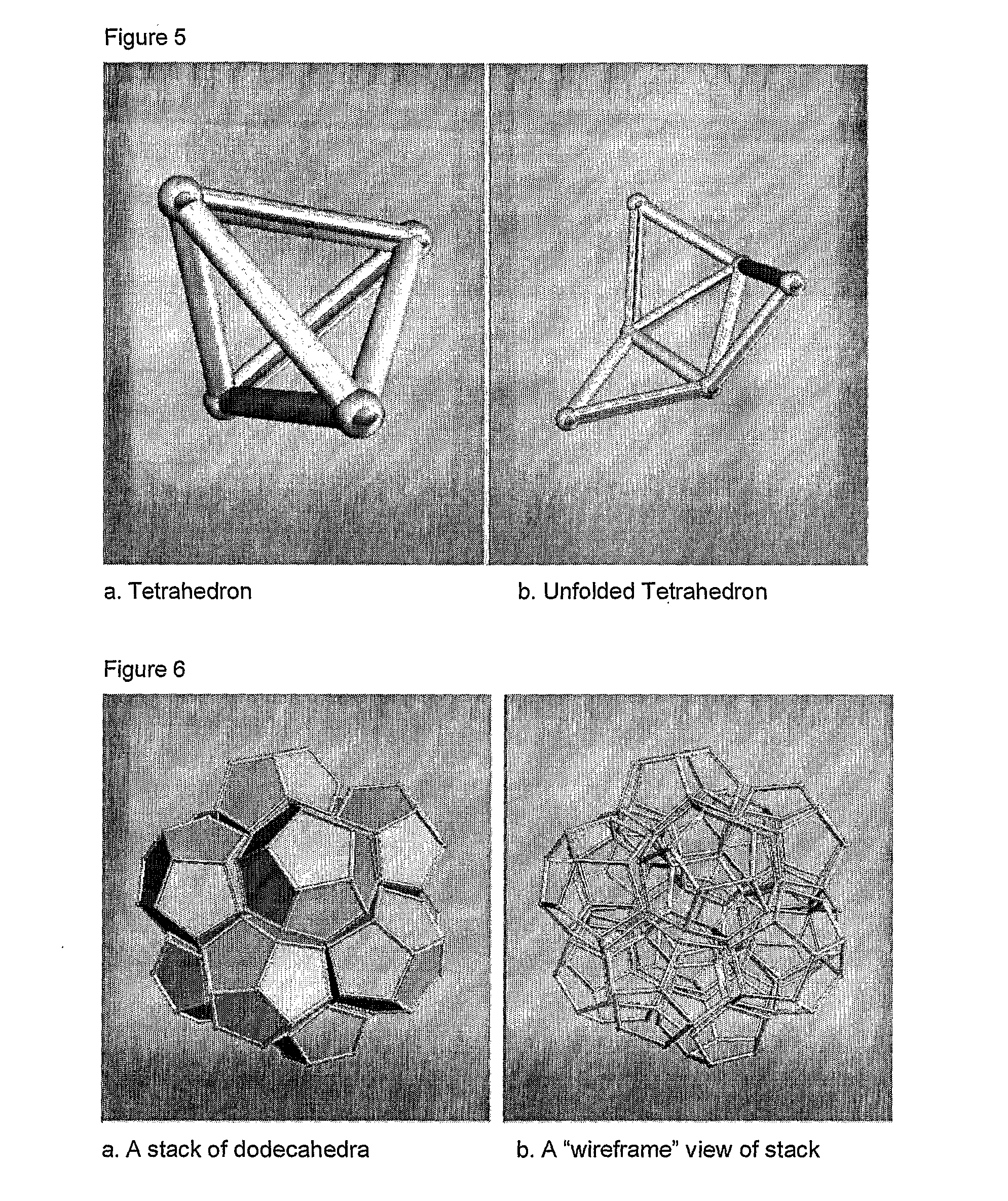
The present invention provides implantable receptacle devices (and methods) for use in bone and tissue regeneration which provide immediate structural stability and strength to a zone where tissue regeneration is required. By virtue of their size, shape and construction, the devices are scalable, modular, structurally stable, self-stacking in three dimensions, can be aggregated to an anatomically accurate shape, and hold various materials delivered into the implant area so as to create a highly regenerative micro-environment. They can be implanted via less invasive surgical procedures, and because they act as external scaffolding as well as being imbedded as an integral part of a matrix for the effective and rapid regeneration of bone and cartilage in vivo, they may provide significant advantages to patients or subjects in terms of reduced pain, faster healing and fewer complications.

Description

FIELD OF INVENTION[0001]The present invention relates to an implant system for the in vivo regeneration of stable bone and cartilage, and in particular to devices specifically shaped as receptacles for scaffold constructs which together form a stable matrix for the regeneration of bone and cartilage in vivo.BACKGROUND OF THE INVENTION[0002]Bone loss is a major problem in trauma and orthopaedic surgery. Everyday, surgeons have to deal with the challenge of patients with major bone loss, either due to trauma, cancer, congenital defects, previous surgery or failed joint replacements.[0003]Bone tissue is composed of a matrix that primarily consists of collagen protein, but is strengthened by deposits of calcium, hydroxyl and phosphate salts, referred to as hydroxyapatite. Inside and surrounding this matrix lie the cells of bone tissue, which include osteoblasts, osteocytes, osteoclasts and bone-lining cells. All four of these cell types are required for building and maintaining a health...

Claims


Application Information

Patent Timeline
IPC IPC(8): A61K35/12A61F2/02A61F2/28A61K9/00C12N5/071A61K38/02A61K38/18A61K38/48A61P19/02A61P19/08A61P43/00B29C35/08
CPCA61F2/28A61F2/30907A61F2002/2817A61F2002/2835A61F2002/30092A61F2002/3028A61F2310/00329A61F2002/3097A61F2002/30985A61F2210/0014A61F2230/0063A61F2310/00011A61F2310/00179A61F2002/3092A61P19/02A61P19/08A61P43/00
Inventor SIVANANTHAN, SURESHANWARNKE, PATRICK HANSSHERRY, EUGENEGOPALAKRISHNAN, KRISH
Owner SIVANANTHAN SURESHAN
Learn More