
In vivo biosensor apparatus and method of use

a biosensor and in vivo technology, applied in the direction of material analysis, positive displacement liquid engine, biomass after-treatment, etc., can solve the problems of inability to detect analytes in situ, cell lysation must be destructive, and the system is quite complicated, so as to achieve stable dosing of insulin, less insulin can be administered, and cost-effective drug administration

Inactive Publication Date: 2004-01-06
UNIV OF TENNESSEE RES FOUND +1
View PDF45 Cites 674 Cited by
  • Summary
  • Abstract
  • Description
  • Claims
  • Application Information

AI Technical Summary

Benefits of technology

In certain embodiments, it may also be desirable to provide a transparent, biocompatible, bioresistant separator that is operably positioned between the phototransducer and the bioreporter.
The device may further comprise a wireless transmitter, an antenna, and a source of nutrients capable of sustaining the bioreporter cells. Likewise the biocompatible container enclosing the bioreporter may further comprise a membrane that is permeable to the analyte but not to the bioreporter cells themselves. Such a semi-permeable membrane permits analytes to flow freely from the bodily fluid into the detector device, but restricts the migration of bioreporter cells from the device into the surrounding tissues or circulatory system of the body in which the device is implanted.
The invention also provides a method of determining the amount of a drug required by a patient in need thereof, such as in the case of giving a diabetic patient an appropriate amount of insulin. The method generally involves implanting within the body of the diabetic patient one or more BBIC devices that are responsive to either glucose, glucagons, insulin, or another glucose metabolite, and determining the amount of insulin required by the patient based upon the levels of the analyte detected in the body fluids by. the device. When the device indicates that higher levels of insulin are required, the appropriate control signal can be sent to the drug delivery system and more insulin is injected into the body. When the device indicates that lower levels of insulin are required, then the appropriate control signal can be sent to the drug delivery system and less insulin can be administered. Such "real-time" monitoring of glucose in the body of the animal permits for controlled release of insulin throughout the day, and obviates the need for daily or more frequent injections of insulin that may either be too much or too little for the particular time of administration. This affords a more cost-effective administration of the drug, and also provides a more stable dosing of the insulin to the patient on an "as needed" basis.

Problems solved by technology

Unfortunately, a limitation of these systems has been that following exposure to the target substance(s), the cells must be destructively lysed and the enzyme(s) isolated.
Because a substrate must be added to the green fluorescent protein constructs to first initiate the light response, however, these systems are quite complicated and offer little advantage for detection of analytes in situ (Prasher, 1995).
Unfortunately, the presence of a glucose oxidase inhibitor molecule in the human bloodstream tended to offset proportionality constants, and made the device unsatisfactorily inaccurate for precise glucose monitoring and control (Gough et al., 1997).
Also limiting was the device's relatively large size (.apprxeq.5.times.7 cm), which negated its usefulness as an implantable device.
Although several smaller needle-type and microdialysis glucose sensors have since been developed to circumvent size limitations (Gough et al., 1997, Selam, 1997), their reliance on a glucose oxidase enzyme-based system limits their overall effectiveness and reliability.
Several nonspecific electrochemical sensors have also been investigated as potential in vivo glucose sensors (e.g., Yao et al., 1994; Larger et al., 1994), but problems including limited sensitivity, instability, and limited long-term reliability have prevented their wide-spread utilization (Patzer et al., 1995).
Despite a significant miniaturization of biosensors during the past decade, they are still relatively large and obtrusive to serve as ideal implantable devices.
Consequently, these cells cannot serve as continuous on-line monitoring devices.

Method used


Image

  • In vivo biosensor apparatus and method of use
  • In vivo biosensor apparatus and method of use
  • In vivo biosensor apparatus and method of use

Examples


first embodiment

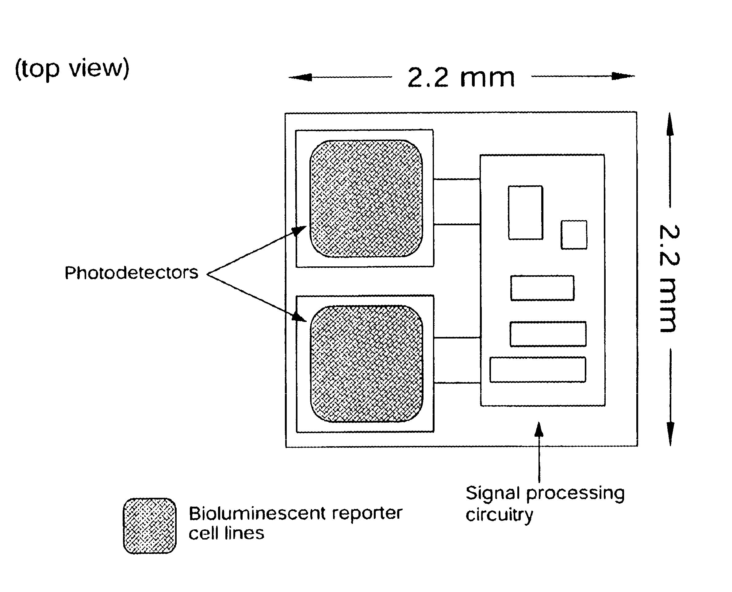
In the first embodiment, the photodetector is fabricated in a standard N-well CMOS process. Shown in FIG. 5A, this detector is formed by connecting the PN junction between the PMOS active region and the N-well in parallel with the PN junction between the N-well and the P-type substrate. The resulting detector is sensitive to light between approximately 400 nm and approximately 1100 nm, a range that encompasses the 450 to 600 nm emission range of most commonly used bioluminescent and chemiluminescent compounds or organisms. In order to meet the requirement that the device have a low background signal, the device is operated with a zero bias, setting the operating voltage of the diode equal to the substrate voltage. The photodiode coating may be formed with a deposited silicon nitride layer or other material compatible with semiconductor processing techniques.

In the second photodetector embodiment, the detector is fabricated in a silicon-on-insulator (SOI) CMOS process. The internal l...

example 1

5.1 Example 1

Construction of a Bioluminescence Reporter for Mammalian Cell Lines

To facilitate the construction of an implantable bioluminescent glucose sensor it will be necessary to create a bioluminescent reporter system that can function without the exogenous addition of substrate for the luciferase reaction. This exogenous addition is due to the complex nature of the production of luciferins for the various eukaryotic luciferases. Cells must be either permeablized or lysed and then treated with an assay solution containing luciferin. Therefore, the present state of bioluminescence reporters used in eukaryotic molecular biology makes them unsuitable for "on-line" monitoring. The firefly luciferase has been used in examining the regulation of L-pyruvate kinase promoter activity in single living rat islet .beta.-cells (Kennedy et al., 1997). However, these cells had to be perfused with Beetle luciferin in order to generate a luminescence response.

To alleviate this limitation, a pre...

example 2

5.2 Example 2

Construction of a Glucose Bioluminescent Biosensor

The firefly luciferase has been used in examining the regulation of L-pyruvate kinase promoter activity in single living islet .beta.-cells (Kennedy et al., 1997). A glucose response element designated the L4 box has been determined to be in the proximal promoter. A 200-bp fragment containing this region was cloned in front of the firefly luciferase (luc) in plasmid pGL3Basic resulting in a glucose reporter plasmid designated p.LPK.Luc.sub.FF. Results resulted in the detection of single cells that were exposed to 16 mM glucose but not 3 mM glucose. However, these cells had to be perfused with Beetle luciferin making it unacceptable for an on-line biosensor. Therefore, a bioluminescent sensor for glucose was constructed by replacing the firefly luciferase in p.LPK.Luc.sub.FF with the fused luxAB gene as described below.


PUM

PropertyMeasurementUnit
wavelengthaaaaaaaaaa
wavelength sensitivityaaaaaaaaaa

Abstract

Disclosed are bioluminescent bioreporter integrated circuit devices that detect selected analytes in fluids when implanted in the body of an animal. The device comprises a bioreporter that has been genetically engineered to contain a nucleic acid segment that comprises a cis-activating response element that is responsive to the selected substance operably linked to a gene encoding a bioluminescent reporter polypeptide. In preferred embodiments, the target analyte is glucose, glucagons, or insulin. Exposure of the bioreporter to the target substance causes the response element to up-regulate the nucleic acid sequence encoding the reporter polypeptide to produce a luminescent response that is detected and quantitated. In illustrative embodiments, the bioreporter device is encapsulated on an integrated circuit that is capable of detecting the emitted light, processing the resultant signal, and then remotely reporting the results. Also disclosed are controlled drug delivery systems capable of being directly or indirectly controlled by the detection device that provide drugs such as insulin to the animal in reponse to the amount of target analyte present in the body fluids.

Description

1.0 BACKGROUND OF THE INVENTION1.1 Field of the InventionThe invention generally relates to the field of implantable diagnostic devices (i.e. devices deployed within the body of an animal) for monitoring one or more target substances, analytes, or metabolites in the animal. More particularly, the invention provides implantable biosensor devices for monitoring and regulating the level of analytes in the tissues and circulatory system of a human. In illustrative embodiments, the apparatus comprises a biosensor that is utilized to monitor the level of blood glucose in a diabetic or hypoglycemic patient. The disclosed sensors may also be used to control or regulate the delivery of a drug or other pharmaceutical agent from an external or an implantable drug delivery system. For example, the device may form part of an artificial pancreas to regulate insulin dosage in response to the level of glucose detected in situ.1.2 Description of Related Art1.2.1 BiosensorsBiosensors are hybrid devic...

Claims


Application Information

Patent Timeline
Patent Type & Authority Patents(United States)
IPC IPC(8): G01N21/76G01N21/64A61B5/00G01N21/03G01N37/00
CPCC12Q1/02C12Q1/66G01N21/763G01N33/74G01N33/84A61B5/0031Y10S435/808Y10S435/849Y10S435/879Y10S436/805Y10S435/909H01L27/00
Inventor SAYLER, GARY S.SIMPSON, MICHAEL L.APPLEGATE, BRUCE M.RIPP, STEVEN A.
Owner UNIV OF TENNESSEE RES FOUND
Learn More