Flexible sensor apparatus

a sensor and flexible technology, applied in the field of flexible mounting bases for sensors, can solve problems such as health risks, and achieve the effect of quick and easy, sufficient stability

Active Publication Date: 2007-03-29
MEDTRONIC MIMIMED INC
View PDF11 Cites 710 Cited by
  • Summary
  • Abstract
  • Description
  • Claims
  • Application Information

AI Technical Summary

Benefits of technology

[0007] The present invention relates to an improved sensor mounting base adapted to provide quick and easy transcutaneous placement of the film sensor on a patient comfortably and with sufficient stability with which to hold the sensor electrodes in direct contact with patient extracellular fluid.
[0009] In certain embodiments, the mounting base is made out of a flexible and breathable material. For example, the mounting base may comprise cloth, band-aid-like material, and the like. Such materials may allow the patient more comfort. The adhesive layer may make it easy to affix or remove the sensor. Re-using the same mounting base would lead to health risks, especially if not sterilized properly. The adhesive of the present invention helps avoid these sanitary risks by allowing the patient to simply replace each adhesive as necessary.
[0010] In a certain embodiments, the mounting base comprises several layers and is smaller than the size of a penny. In one embodiment, the entire mounting base is about the thickness of a penny with a diameter that is about half that of a penny. In this embodiment, the mounting base of the sensor has an outer flexible layer, a sealing layer, a semi-rigid housing, and a flexible adhesive layer. The semi-rigid portion helps to substantially stabilize the entire base, specifically around the needle insertion area. In one embodiment, the semi-rigid portion may have the flexibility and rigidity of a guitar pick. Stabilizing the needle insertion area may help to ensure safe, stable entry and exit for needle at infusion site.
[0011] In further embodiments, the mounting base is configured to be in a slim configuration so that it can fit closer against the patient's body when worn. The slim shape provides more comfort while being less conspicuous, for example, when worn under clothes.
[0014] During insertion, the insertion needle and the protective cannula cooperatively protect and guide the sensor to the desired transcutaneous placement position. The insertion needle can then be withdrawn, whereupon the slotted needle geometry permits the insertion needle to slide over and longitudinally separate from the second portion of the cannula, thereby leaving the cannula and sensor therein at the selected infusion site.
[0016] In particular embodiments, a connector fitting is included to provide a convenient and relatively simple structure for anchoring the flexible cable in electrical coupled relation with a telemetry unit, such as a monitor. In such embodiments, the connector fitting may be positioned on the flexible cable, some distance away from the sensor site, rather than being positioned directly on the sensor set. In embodiments where the connector fitting is located away from the sensor set, the flexible cable is easily accessed for periodic removal and replacement of the monitor, without requiring removal or replacement of other system components. Additionally, because the connector fitting is located away from the sensor set, the attached monitor may be stored away from the infusion site. In this configuration, the potential aggravation of the infusion site or contamination of the monitor from the infusion site is minimized.

Problems solved by technology

Re-using the same mounting base would lead to health risks, especially if not sterilized properly.

Method used


Image

  • Flexible sensor apparatus
  • Flexible sensor apparatus
  • Flexible sensor apparatus

Examples


Embodiment Construction

[0032] In the following description, reference is made to the accompanying drawings which form a part hereof and which illustrate several embodiments of the present inventions. It is understood that other embodiments may be utilized and structural and operational changes may be made without departing from the scope of the present inventions.

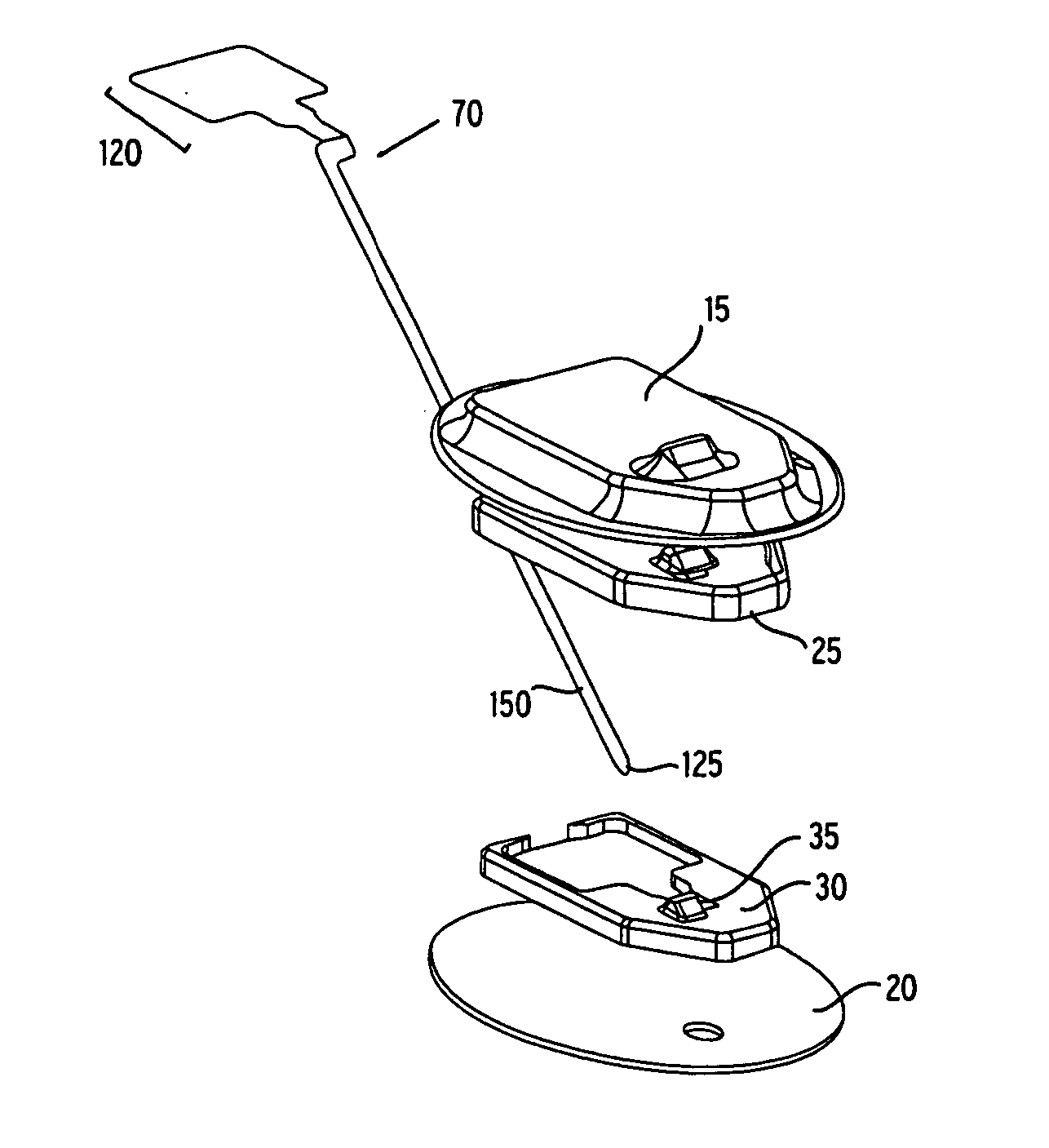
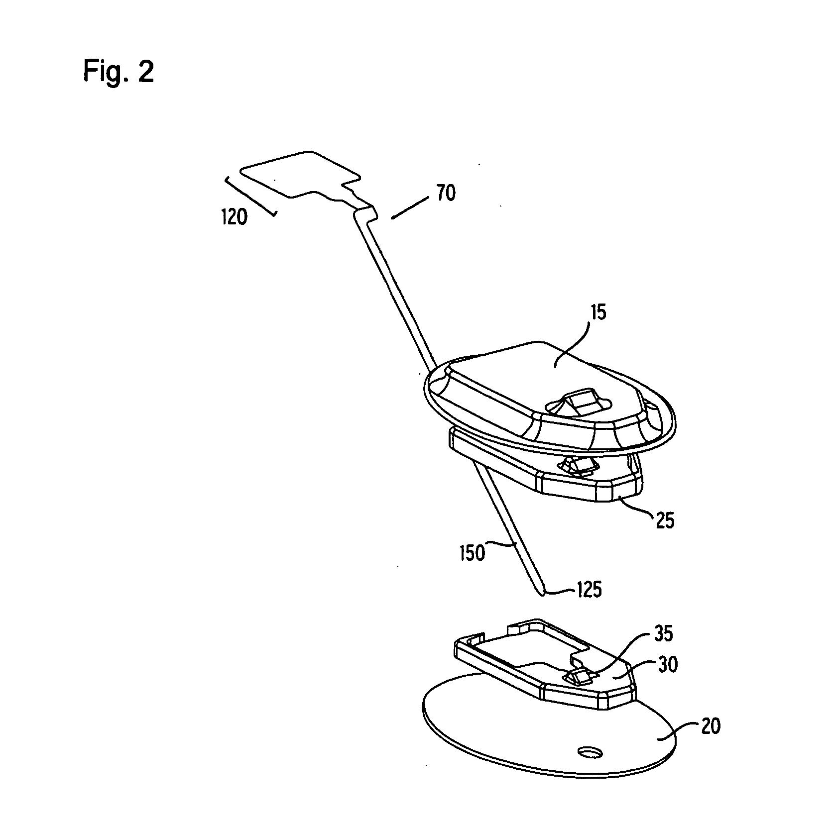
[0033] In accordance with embodiments of the invention, a flexible mounting base for a sensor is provided for measuring an analyte, such as blood glucose, of a patient. The flexible mounting base may be used with different types of sensors, including a flexible analyte sensor. The sensor set is placed at a selected site on the patient's body and stabilized by the flexible mounting base and a flexible adhesive layer that holds the sensor at the infusion site in a comfortable but stable manner.

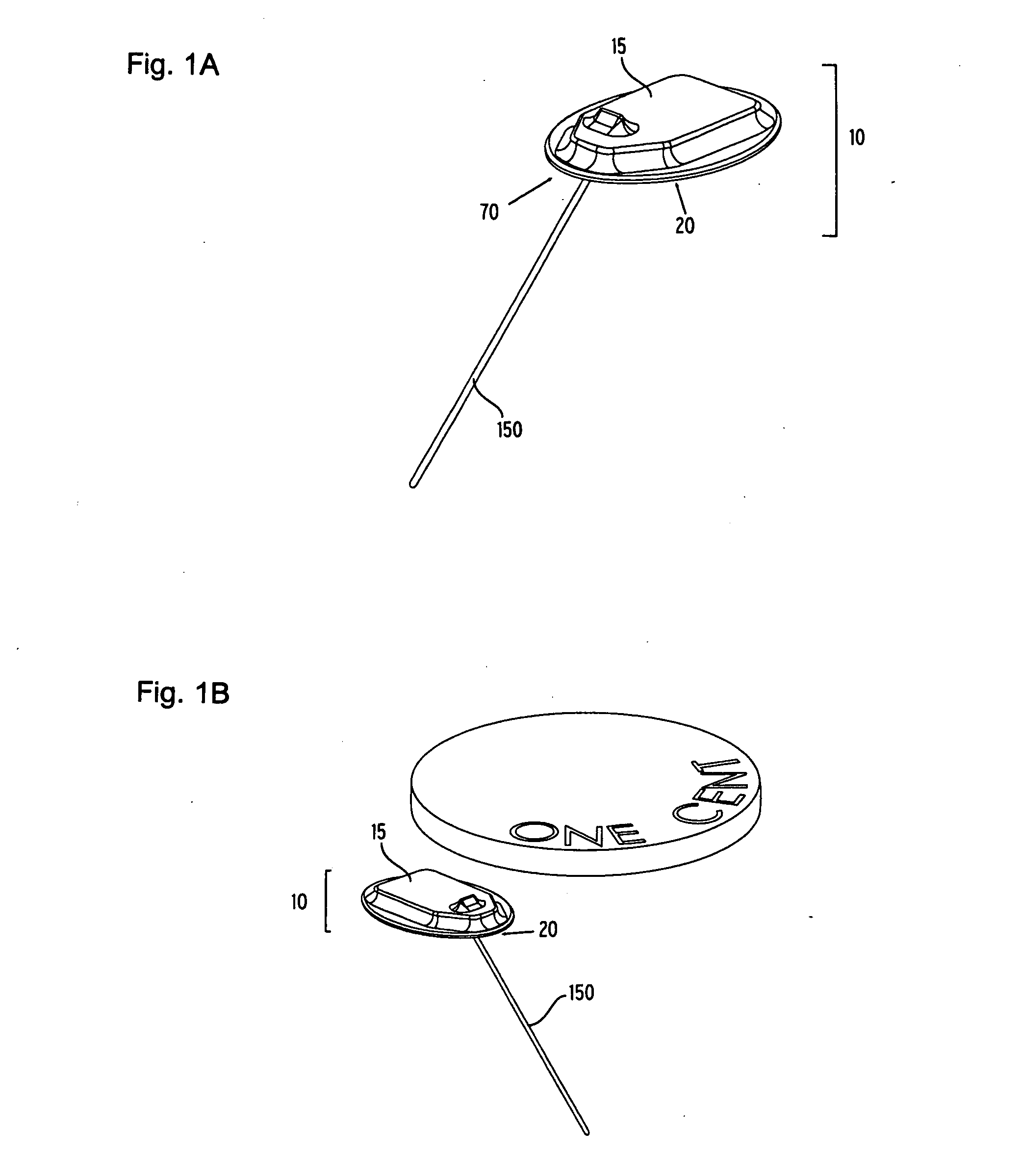
[0034] In one preferred embodiment, as shown in FIGS. 1a and 1b, the flexible mounting base 10 has a relatively flat shape and is smaller than a penny. In ...


PUM


Abstract

A flexible mounting base to hold a sensor at an infusion site, the sensor being a removable in vivo sensor for monitoring analyte concentration level in a patient, such as blood glucose (BG) level. The mounting base comprises a flexible adhesive that anchors the flexible sensor set at an infusion site to provide stability for the sensor set in a convenient and comfortable manner. Placement of the mounting base onto the patient's skin causes the insertion needle to pierce the skin for transcutaneous placement of the cannula with the sensor therein. The insertion needle can then be withdrawn to leave the cannula and sensor at the selected insertion position, with the distal segment of the sensor being exposed to patient extracellular fluid via apertures formed in the cannula.

Description

FIELD OF THE INVENTION [0001] 1. Field of the Invention [0002] This invention relates generally to devices and methods for placing a sensor at a selected site within the body of a patient. More specifically, this invention relates to a flexible mounting base for a sensor adapted for convenient and comfortable transcutaneous positioning of the sensor electrodes to obtain analyte readings, for example, blood glucose (BG) readings. [0003] 2. Description of Related Art [0004] Sensors are generally known in the art for use in a variety of specialized sensor applications. For example, thin film electrochemical sensors have been used to test analyte levels in patients. Such thin film sensors generally comprise one or more thin conductors applied by photolithography mask and etch techniques between thin layers of a nonconductive film material, such as polyimide film. The conductors are shaped to define distal segment ends having an appropriate electrode material thereon, in combination with...

Claims


Application Information

Patent Timeline
Patent Type & Authority Applications(United States)
IPC IPC(8): A61B5/00A61B5/05
CPCA61B5/14532A61B5/14865A61B2562/164A61B2017/3407A61B5/6849
Inventor SHAH, RAJIVGOTTLIEB, REBECCA K.LARSON, ERIC A.
Owner MEDTRONIC MIMIMED INC
Why Eureka
Try Eureka