Endoscope and instrument lifting operation device for the same

Active Publication Date: 2011-03-31
HOYA CORP
View PDF21 Cites 7 Cited by
  • Summary
  • Abstract
  • Description
  • Claims
  • Application Information

AI Technical Summary

Benefits of technology

[0008]Since the braking mechanism of the instrument lifting operation device is required to have a function of maintaining a stationary state of the operation wire, the barking mechanism needs to have a static frictional resistance of a certain level or more. However, the braking mechanism described in JP S49-74788U causes a relatively large amount of dynamic frictional resistance in addition to the static frictional resistance. Therefore, the strength of the operation force for drawing the operation wire from the operation unit side to lift the tip of the treatment instrument becomes increases. As a result, operability of the endoscope deteriorates.
[0009]The present invention is advantageous in that it provides an instrument lifting operation device for an endoscope configured to be effectively arranged in an operation unit without interfering with another mechanism to be provided in the operation unit, to be able to reduce the dynamic frictional resistance relative to the static frictional resistance, and thereby to enable an operator to smoothly conduct an operation for lifting a treatment instrument by a small force.
[0011]With this configuration, it becomes possible to effectively arrange the instrument lifting operation device in the operation unit without interfering with another mechanism to be provided in the operation unit. Furthermore, it becomes possible to reduce the dynamic frictional resistance relative to the static frictional resistance, and thereby to enable an operator to smoothly conduct an operation for lifting a treatment instrument by a small force.

Problems solved by technology

As a result, movement of the operation wire to move back to the tip side can be restricted by the frictional resistance caused between the frictional plate and the sliding plate.
Such a configuration may badly affect arrangement of other operation mechanisms (e.g., a bending operation mechanism) in the operation unit.
However, the braking mechanism described in JP S49-74788U causes a relatively large amount of dynamic frictional resistance in addition to the static frictional resistance.
As a result, operability of the endoscope deteriorates.

Method used


Image

  • Endoscope and instrument lifting operation device for the same
  • Endoscope and instrument lifting operation device for the same
  • Endoscope and instrument lifting operation device for the same

Examples


Embodiment Construction

[0027]Hereinafter, an embodiment according to the invention is described with reference to the accompanying drawings.

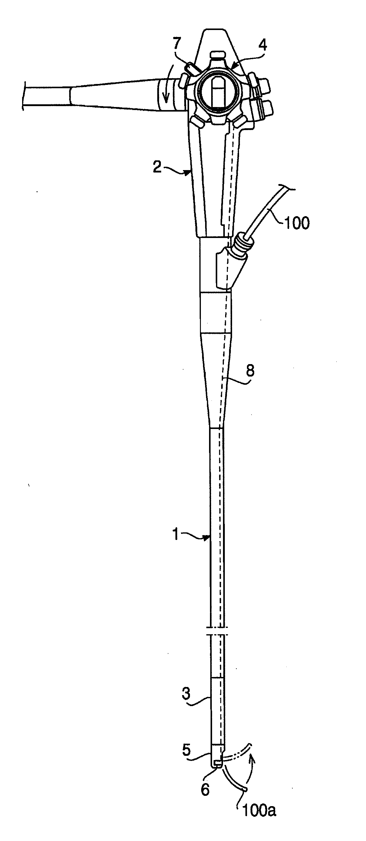
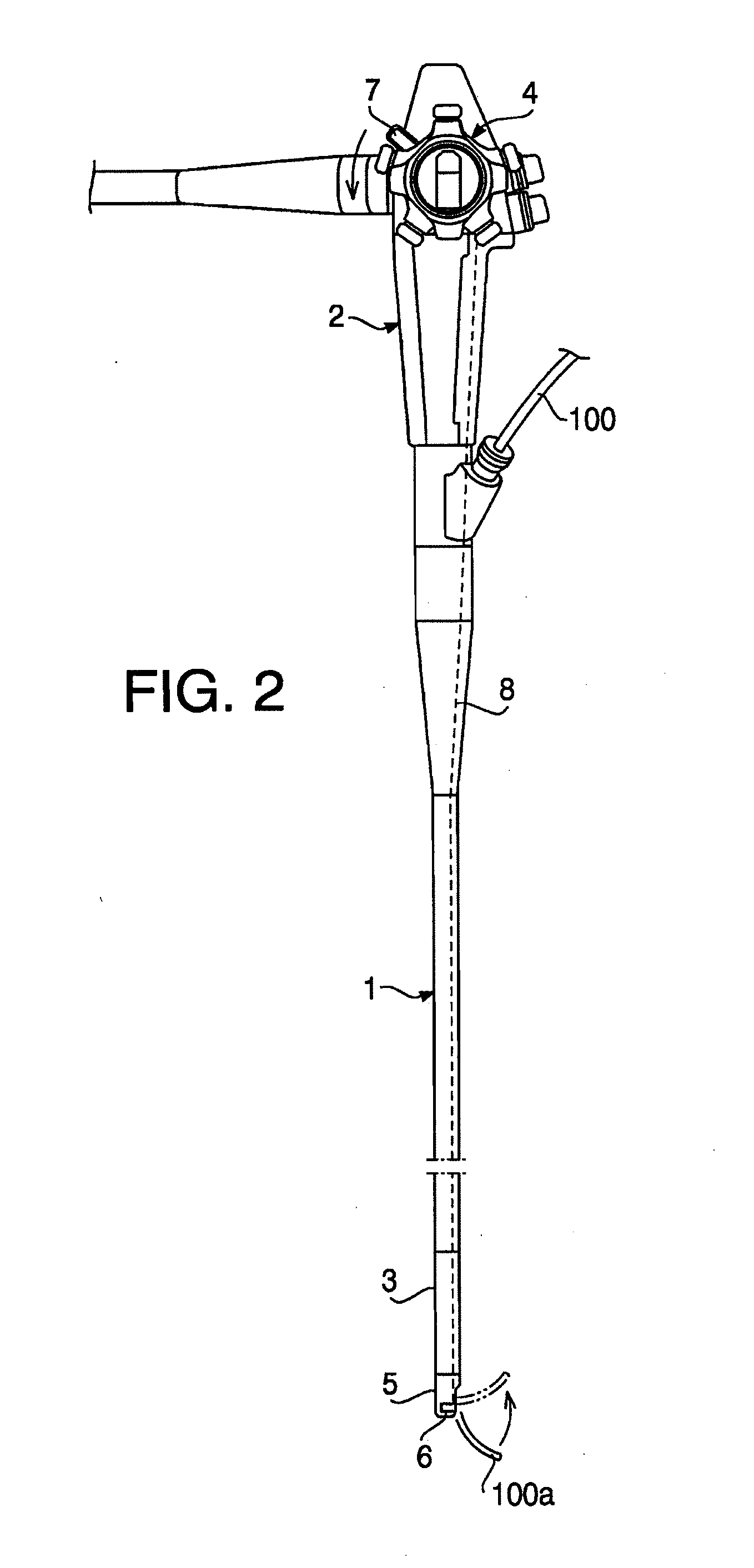
[0028]FIG. 2 illustrates an entire configuration of an endoscope. In the configuration shown in FIG. 2, a proximal end of an elastic insertion tube 1 having elasticity is connected to a lower end of an operation unit 2, and a bending part 3 connected to a tip end of the elastic insertion tube 1 is configured to be bent at a desired angle in a desired direction through remote control from a bending operation device 4 provided on the operation unit 2.

[0029]Reference number 5 represents a tip part body 5 which is connected to the tip of the bending part 3 to form a tip part of an insertion unit. The insertion unit is formed of the elastic insertion tube 1, the bending part 3 and the tip part body 5. In the insertion unit (i.e., in the elastic insertion tube 1, the bending part 3 and the tip part body 5), an instrument-inserting channel (not shown) is arranged so that a t...


PUM


Abstract

An instrument lifting operation device including: an operation wire drawing mechanism configured to draw an proximal end of an operation wire connected to an instrument lifting piece; and a braking mechanism configured to restrict movement of the operation wire toward the tip side, wherein the braking mechanism includes: a fixed wall; and a spring arranged to be able to rotate about an axis together with an instrument lifting operation member in a state where the spring is elastically pressed against an inner circumferential surface of the fixed wall. When the instrument lifting operation member is operated to rotate about the axis, the wire coupling member rotates about the axis and the operation wire moves forward and backward in a state where the spring contacts and slides on the inner circumferential surface of the fixed wall to generate frictional resistance at a contacting part.

Description

BACKGROUND OF THE INVENTION[0001]The present invention relates to an instrument lifting operation device for an endoscope.[0002]Endoscopes provided with an instrument lifting piece for controlling the protruding direction of the tip of a treatment instrument inserted into an instrument-insertion channel have been used. In such an endoscope, an instrument lifting operation device is provided in an operation unit to be operated by an operator. The instrument lifting operation device serves to remotely control the instrument lifting piece from the operation unit to which a proximal end of an insertion unit is connected.[0003]In the instrument lifting operation device, an operation wire drawing mechanism for manually drawing a proximal end of an operation wire whose tip is connected to the instrument lifting piece is provided. In the state where the tip of the treatment instrument is lifted by the instrument lifting piece, a force for restoring the instrument lifting piece to an origina...

Claims


Application Information

Patent Timeline
IPC IPC(8): A61B1/00
CPCA61B1/00098A61B1/00133A61B1/0057A61B1/018G02B23/2476A61B1/0052
Inventor MARUYAMA, YOSHINORI
Owner HOYA CORP
Why Eureka
Try Eureka