Method and device for tightening joints

Active Publication Date: 2011-04-07
ATLAS COPCO INDAL TECHN AB
View PDF12 Cites 22 Cited by
  • Summary
  • Abstract
  • Description
  • Claims
  • Application Information

AI Technical Summary

Benefits of technology

[0013]This has the advantage that the assembly device can be made to operate in a manner that is more adapted to the individual operator, since by detecting the angular rotation of said device with respect this axis, the speed of th

Problems solved by technology

However, such tools can, in particular with regard to high-torque joints (e.g., in the order of 50 Nm or more), impose undesired jerks of the tool when the torque starts to rise if the operator is unprepared to the sudden torque increase.
Such jerks can be very uncomfortable to the operator, and also be a risk of danger if the operator is subject to a powerful jerk of the tool, e.g. when standing close to a wall or sharp objects.
Although the above described methods are cap

Method used


Image

  • Method and device for tightening joints
  • Method and device for tightening joints
  • Method and device for tightening joints

Examples


Embodiment Construction

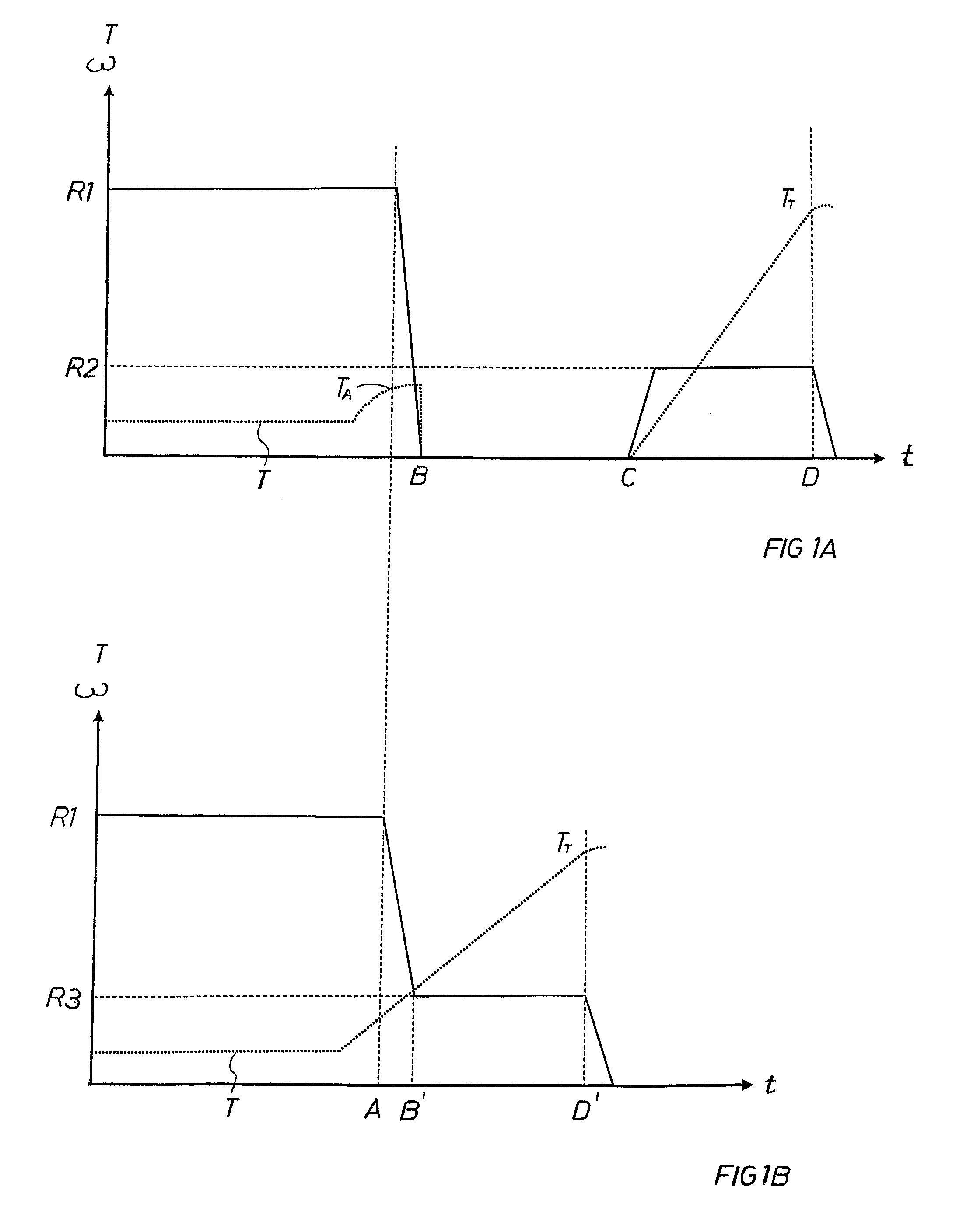
[0020]In order to clarify the advantages of the present invention, the above mentioned two prior art methods of tightening fasteners will first be briefly described with reference to FIGS. 1A-B.

[0021]In FIG. 1A is shown a graph of the variation in time of the tightening torque and the rotational speed of the tightening during a typical tightening process. The solid line represents the rotational speed of the tightening, and the dashed line represents the tightening torque. As can be seen in the figure, the method starts with a high, substantially constant rotational speed R1, which is maintained for as long as the tightening torque is below a first threshold TA, i.e. to point A in the figure. At point A it is consequently detected that the torque has started to rise, and when this is detected, the rotational speed of the tightening is reduced to zero, point B.

[0022]The point A can, is generally a point where the tightening torque quickly has started to rise in a manner that is detec...


PUM


Abstract

An electric assembly device for tightening of fastener includes a housing and a rotation motor which is drivingly connected to an output shaft. The output shaft has a forward portion extending out of the housing, and is adapted to carry a coupling device for releasable coupling with a fastener during tightening, which is to be performed along a first rotation axis. The device is adapted to determine an angular displacement of the housing with respect to the first rotation axis during tightening of the fastener, and to control the rotation speed of the motor during tightening based on the determined angular displacement of the housing.

Description

FIELD OF THE INVENTION[0001]This invention relates to devices for tightening threaded fasteners to a desired tightening force or clamping force. In particular, the present invention relates to an electric assembly device for tightening of fasteners according to the preamble of claim 1. The present invention also relates to a method for tightening fasteners according to the preamble of claim 11.BACKGROUND OF THE INVENTION[0002]The increasing requirement of rapid assembly in assembly plants such as manufacturing plants has resulted in the development of sophisticated assembly tools. For example, with regard to the tightening of joints, a threaded fastener such as a nut, screw or bolt often has to be rotated a number of turns with a relatively low torque prior to the fastener reaching a point where the joint actually starts to tighten and the torque thereby starts to rise.[0003]Consequently, it is highly desirable that the initial threadening or running down phase can be carried out as...

Claims


Application Information

Patent Timeline
IPC IPC(8): B25B21/00B25B23/00
CPCB25B21/00B25B23/147B25B23/14
Inventor ELSMARK, KARL JOHAN LARSPERSSON, LARS MAGNUS
Owner ATLAS COPCO INDAL TECHN AB
Why Eureka
Try Eureka