transceiver

a transceiver and receiver technology, applied in the field of transceivers, can solve the problems of increasing the number of control modes of a device, incompatible devices, and inability to provide new transceivers as drop-in replacements for known transceivers, and achieve the effect of improving the accuracy of detecting wake-up signals and less noisy signals

Active Publication Date: 2011-04-07
NXP BV
View PDF7 Cites 19 Cited by
  • Summary
  • Abstract
  • Description
  • Claims
  • Application Information

AI Technical Summary

Benefits of technology

[0011]In this way, the wake-up detector of the transceiver can be configured in accordance with signals received at the transmit pin on a device-side of the transceiver. Configuring the transceiver in accordance with a signal received at the device-side of the transceiver as opposed to the network-side of the transceiver can take advantage of a

Problems solved by technology

More complex interfaces, such as I2C and SPI, are known to increase the number of control modes for a device.
Disadvantages associated with these examples can include a more

Method used


Image

  • transceiver
  • transceiver
  • transceiver

Examples


Embodiment Construction

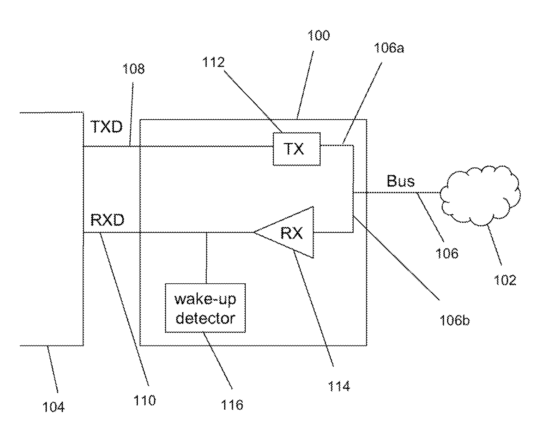
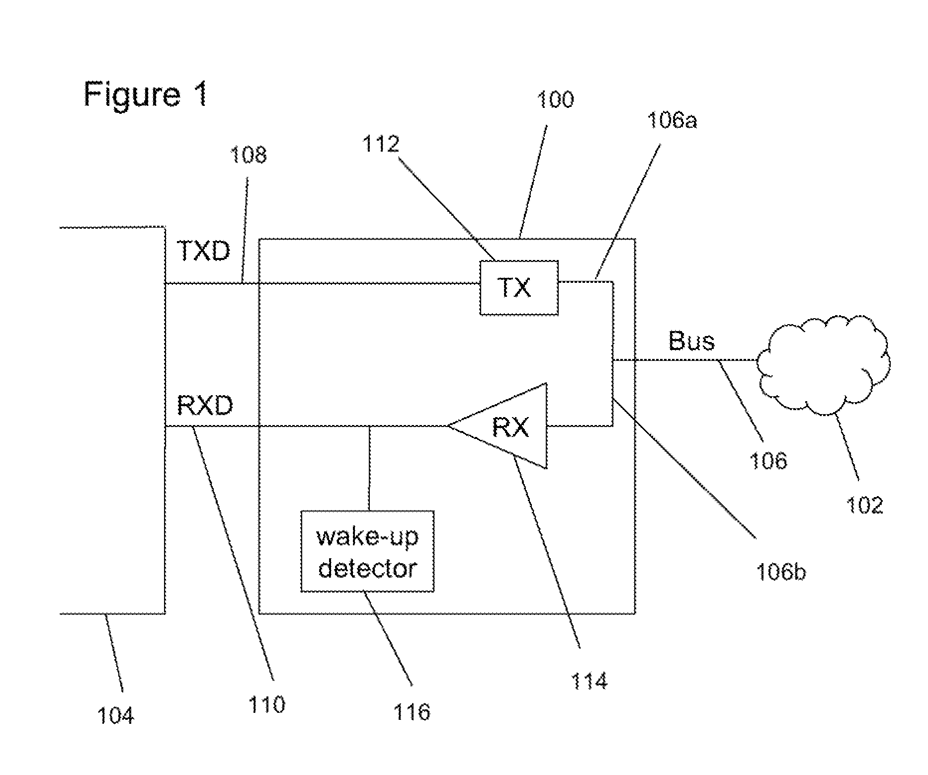
[0021]In some embodiments, the transceiver may comprise two bus pins, or any other number of bus pins. It will be appreciated that the number of bus pins may be dependent upon the type of network that is being used. For example, CAN and FlexRay networks are dual wire bus systems, whereas LIN or Single-wire CAN have a single bus wire.

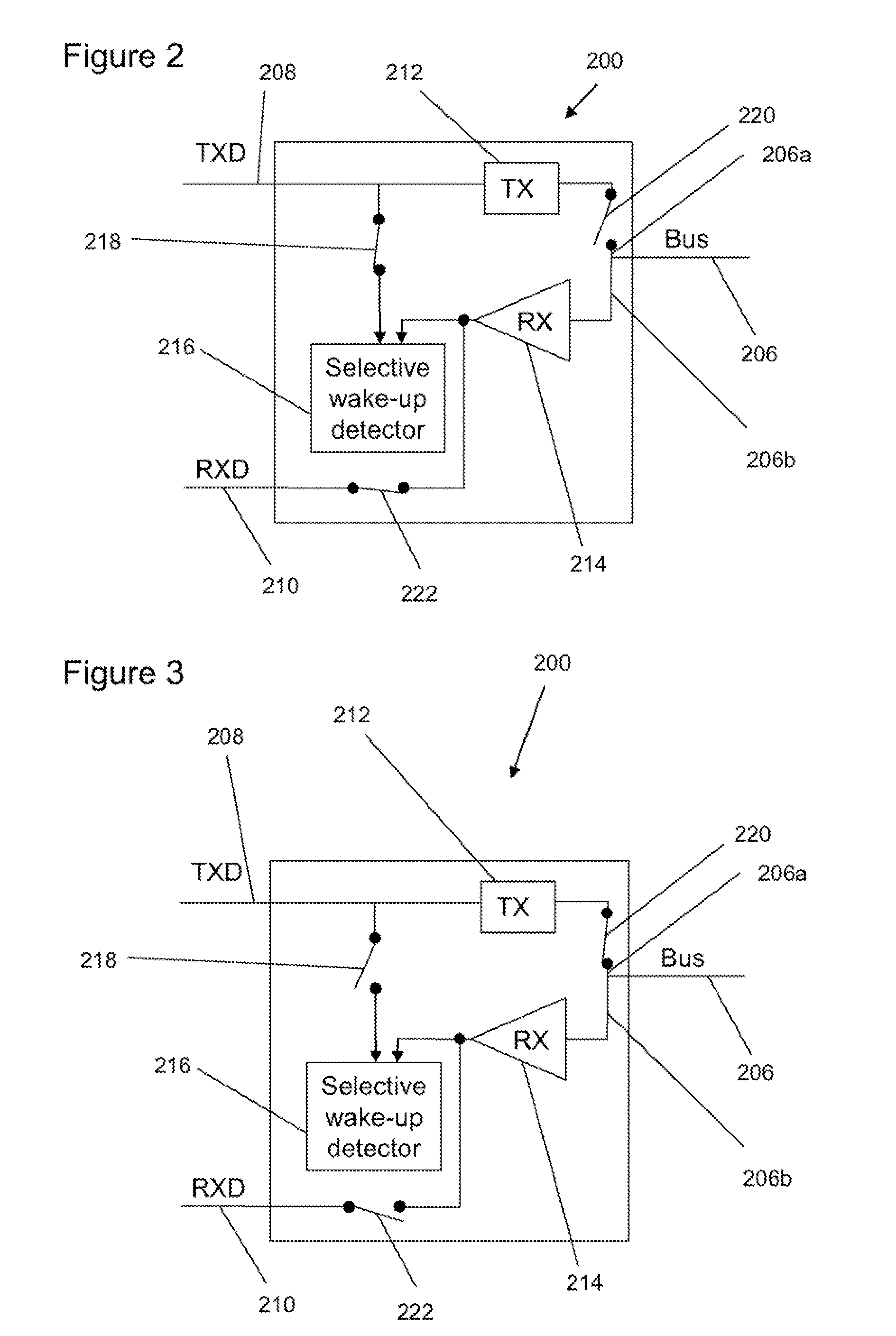
[0022]The one or more switches may be further operable to put the transceiver in a second mode of operation, and, in the second mode of operation: the wake-up detector is connected to the bus pin; and the wake-up detector is configured to monitor signalling received at the bus pin in order to identify the activated wake-up code. The second mode of operation may be considered as a scanning / monitoring mode of operation in which signals on the network are monitored for the wake-up code that was activated in the first mode of operation.

[0023]The wake-up detector may be configured to cause the transceiver to enter a third mode of operation upon identifying th...


PUM


Abstract

A transceiver comprising a transmit pin configured to receive a signal from a microcontroller, a receive pin configured to transmit a signal to a microcontroller and a bus pin configured to transmit and receive signalling to/from a network.

Description

[0001]This application claims the priority of European patent application no. 09252366.1, filed on Oct. 6, 2009, the contents of which are incorporated by reference herein.BACKGROUND OF THE INVENTION[0002]Automotive bus transceivers normally provide a simple interface for mode control of a device / microcontroller in a network. Such devices / microcontrollers can include door control units, dashboard controllers, etc. A typical standard transceiver makes use of up to two dedicated mode control pins, and this means that there are usually not more than four different states of operation.[0003]More complex interfaces, such as I2C and SPI, are known to increase the number of control modes for a device. Also, it is known to add additional dedicated mode control pins in excess of the typical two control pins. Disadvantages associated with these examples can include a more expensive device that is incompatible with earlier devices, and this means that such a new transceiver may not be provided...

Claims


Application Information

Patent Timeline
IPC IPC(8): H04Q5/22
CPCH04L12/40032H04L2012/40273H04L12/40039
Inventor WAGNER, MARTIN
Owner NXP BV
Why Eureka
Try Eureka