Light emitting device

a technology of light emitting devices and light sources, which is applied in the direction of semiconductor devices for light sources, point-like light sources, lighting and heating apparatus, etc., can solve the problems of many problems the instrument cannot give the required performance, and users who are accustomed to the light from the conventional light emitting devices which provide circular irradiation areas feel uncomfortable in the square irradiation area

Inactive Publication Date: 2011-04-07
PHOENIX ELECTRIC CO
View PDF6 Cites 8 Cited by
  • Summary
  • Abstract
  • Description
  • Claims
  • Application Information

AI Technical Summary

Benefits of technology

According to the present invention, a light emitting device whose the irradiation directions of large amount of light from several LED elements can be easily controlled with a reflector can be provided. And the light emitting device can be applied as a replacement light emitting device for conventional optical instrument without any problems due to its circular irradiation area same as of conventional light emitting device and can be applied for general lighting without giving uncomfortable feeling to users.

Problems solved by technology

However, the “square” irradiation area has many problems.
When the above light emitting device 1 is applied as a replacement light emitting device for such a conventional optical instrument, the instrument can not give a required performance, due to a difference of irradiation area shape.
Furthermore, when the light emitting device 1 is applied as a replacement light emitting device for general lighting, users who are accustomed to the light from the conventional light emitting devices which provide circular irradiation areas feel uncomfortable to the square irradiation area.

Method used


Image

  • Light emitting device
  • Light emitting device
  • Light emitting device

Examples


first embodiment

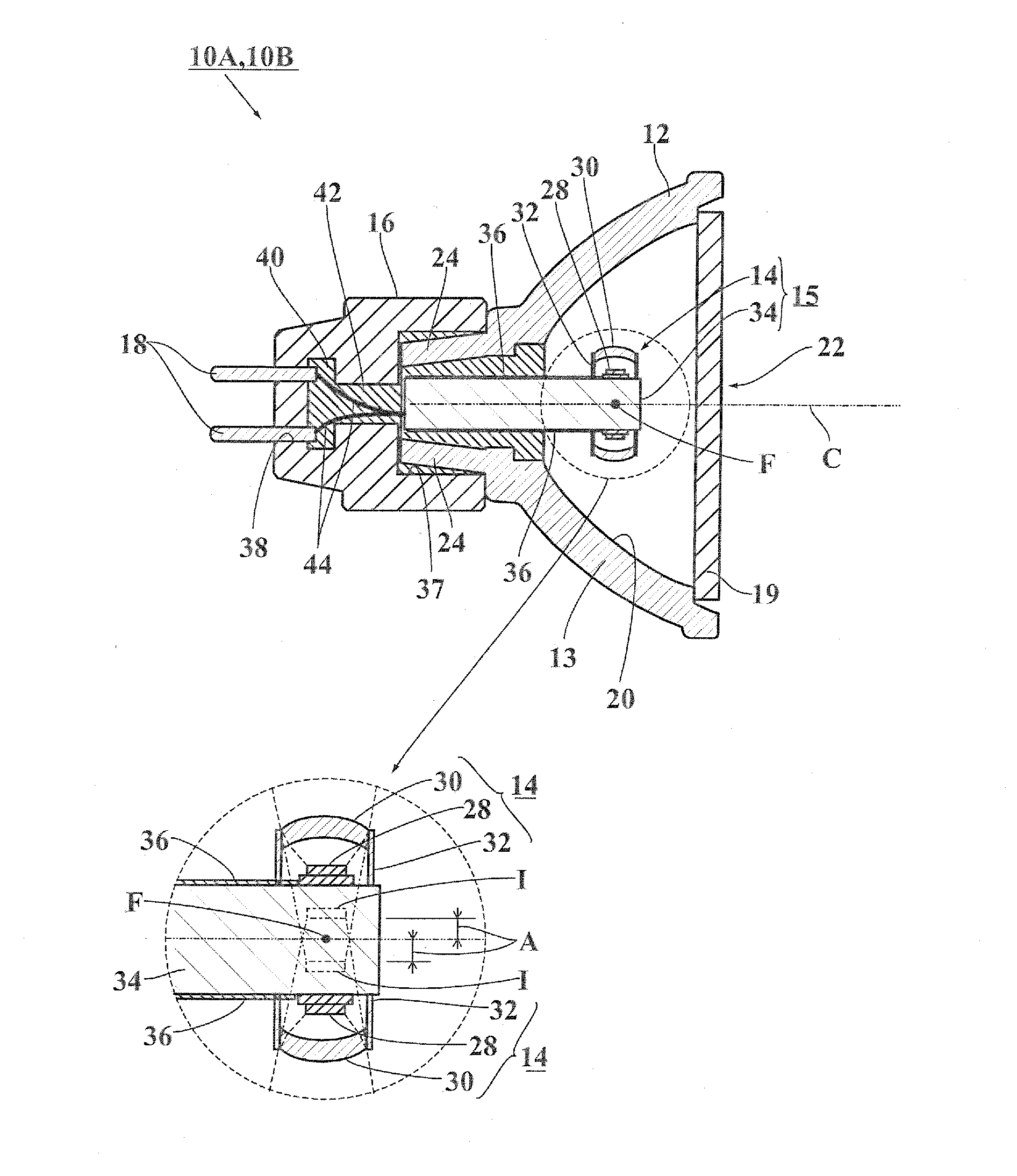
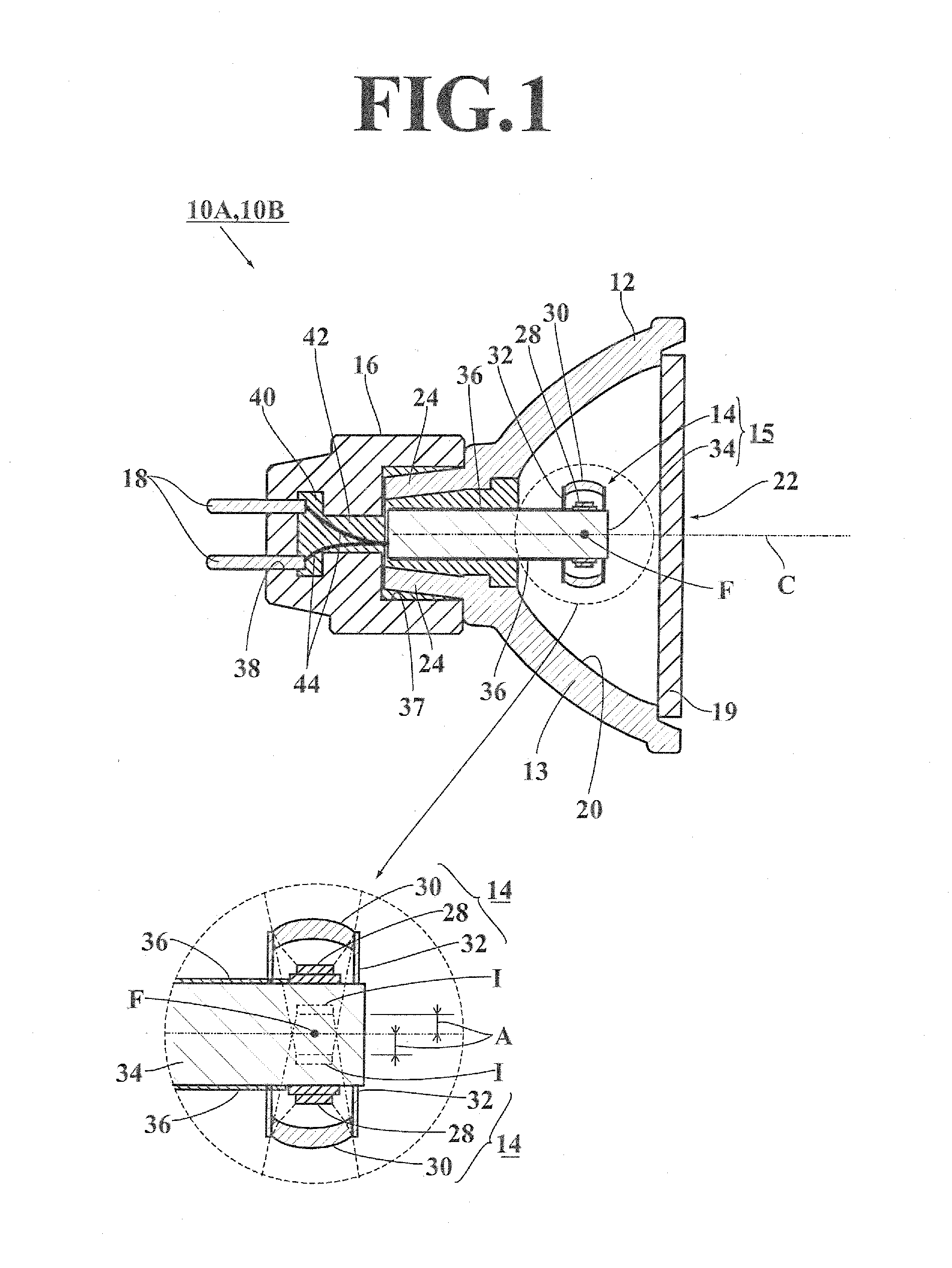
The light emitting device 10A according to the first embodiment comprises, as shown in FIG. 1 and FIG. 2, a concave reflector 12; a light emitting unit 15 having four illuminators 14 and an illuminator holder 34 supporting the illuminators 14; a holder 16; and power feeding terminals 18.

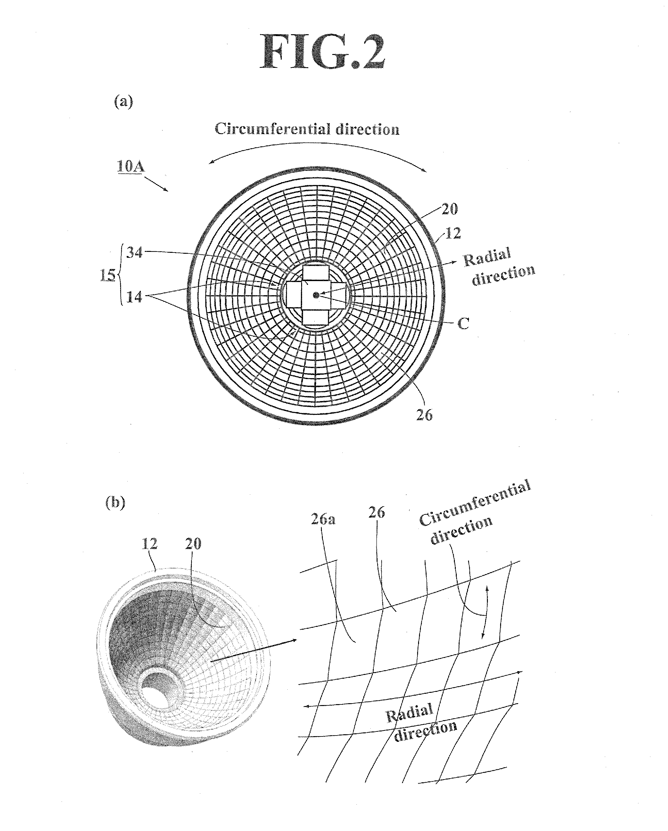
The reflector 12 comprises a reflecting surface 20 formed inside of the reflector 12; a light-emitting opening 22 through which the light reflected on the reflecting surface 20 pass; a central fixing cylindrical portion 24 being inserted into the holder 16. The central fixing cylindrical portion 24 is arranged at bottom center part, which faces to the light-emitting opening 22, of the reflecting surface 20. And a central axis C of the reflecting surface 20 is a straight line that passes through a center of the reflector 12 and is in a direction perpendicular to the light-emitting opening 22.

The reflector 12 is made of glass or aluminum, for example. The reflector 12, which is made of aluminum, has th...

second embodiment

In the same manner as the first embodiment, the light emitting device 10B in the second embodiment comprises a concave reflector 12; a light emitting unit 15 having four illuminators 14 and an illuminator holder 34 supporting the illuminators 14; a holder 16; and power feeding terminals 18. The light emitting device 10B has some differences from the light emitting device 10A as follows; (1) the shapes of the tiny reflecting surfaces 26 of the reflecting surface of the reflector 12 are, as shown in FIG. 5, hexagon in planar view; (2) the value “A / B” that a distance “A” between the virtual image I and the focal point F is divided by the length of outer edge “B” of the LED element 28 is not less than 0.05 and not more than 0.42.

As a specific embodiment of the second embodiment of the light emitting device 10B, two types of the light emitting device 10B as shown in Table4. Table 5 and 6 show how “a shape of the irradiation area”, “brightness at an intersection, which is a center of the ...


PUM


Abstract

A light emitting device 10A comprises: a bowl-shaped reflector 12 having a focal point F; and illuminators 14 have LED elements 28 being square in planar view and lenses 30 forming virtual images I of the LED elements 28 behind the LED element 28; wherein a position of each of the virtual images I from the lens 30 is farther than a position of the focal point F from the lens 30; when a distance A between the virtual image I and the focal point F and a length of outer circumference B of the LED element 28 being square in planar view are assumed, a value of A divide B (A/B) is not less than 0.08 and not more than 0.42.

Description

BACKGROUND OF THE INVENTION1. Field of the InventionThe present invention relates to a light emitting device used for a light source for general lighting at home, commercial facility, and exhibition facility, for example, or optical instrument.2. Description of the Related ArtA light-emitting diode “LED”, which has good points such as low power consumption and long operating life as against a past incandescent lamp, for example a halogen lamp, is widely used, because people become more ecology conscious. And people consider that using the LED is one policy for the energy-saving strategies. Particularly, it is highly required to use the LED as an alternate item of the incandescent lamp.In contrast, the LED has a problem that its amount of light is lower than amount of light of the incandescent lamp. Accordingly, a light emitting device which can emit much light with several LEDs has been developed to cover this problem (See Patent Document 1: Japanese Laid-Open Patent Publication No....

Claims


Application Information

Patent Timeline
Patent Type & Authority Applications(United States)
IPC IPC(8): F21V1/00
CPCF21V5/04F21K9/137F21Y2101/02F21K9/233F21Y2115/10
Inventor NAKAGAWA, ATSUJIIKEDA, TOMIHIKOWATANABE, KANA
Owner PHOENIX ELECTRIC CO
Why Eureka
Try Eureka