Energy collection systems and methods

Active Publication Date: 2011-04-14
HEWLETT-PACKARD ENTERPRISE DEV LP
View PDF21 Cites 18 Cited by
  • Summary
  • Abstract
  • Description
  • Claims
  • Application Information

AI Technical Summary

Benefits of technology

[0003]An energy collection system is provided. The system can include an energy collection device and an energy concentration device disposed proximate at least a portion of the energy collection device. The energy concentration device includes a no

Problems solved by technology

Despite the vast potential energy source provided by the electromagnetic radiation released by the sun, efficient use of solar energy is hampered due to the diffuse nature of the energy received at the earth's surface.
As such, facilities ca

Method used


Image

  • Energy collection systems and methods
  • Energy collection systems and methods
  • Energy collection systems and methods

Examples


Embodiment Construction

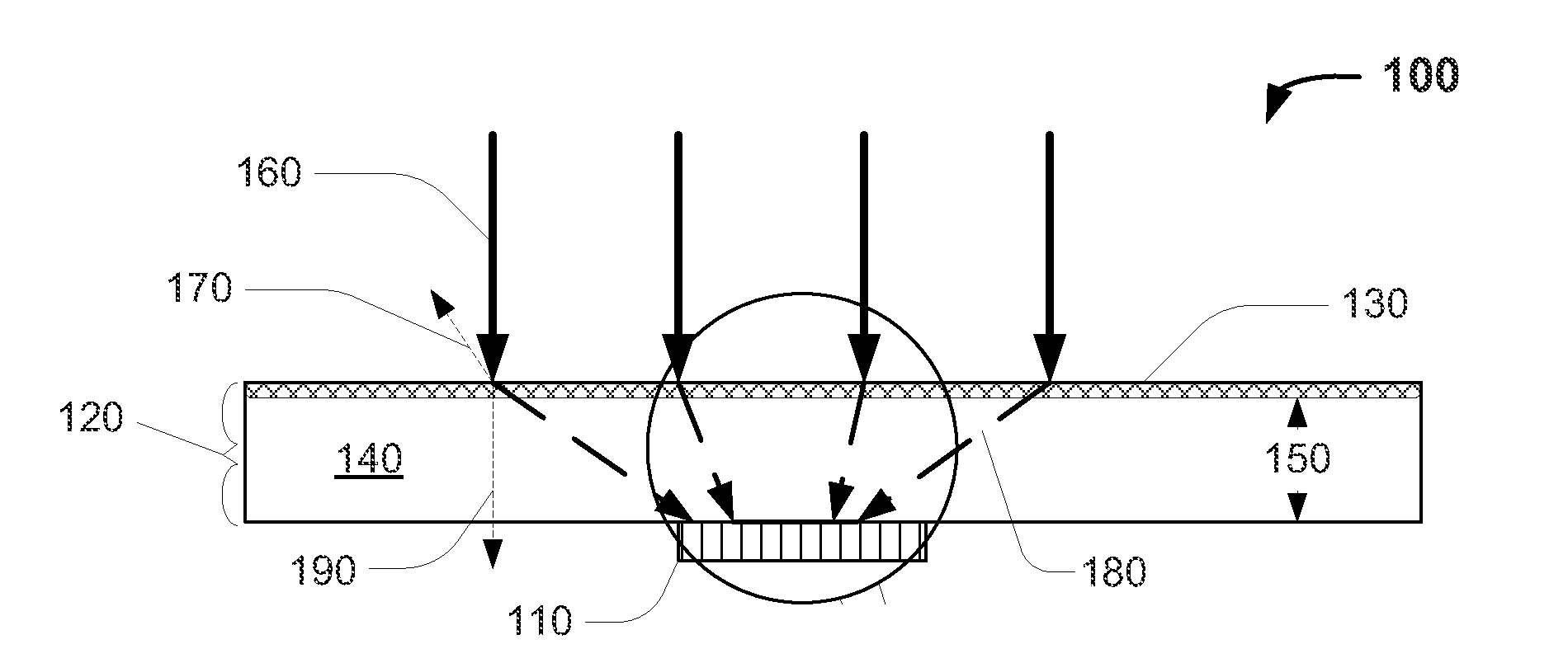
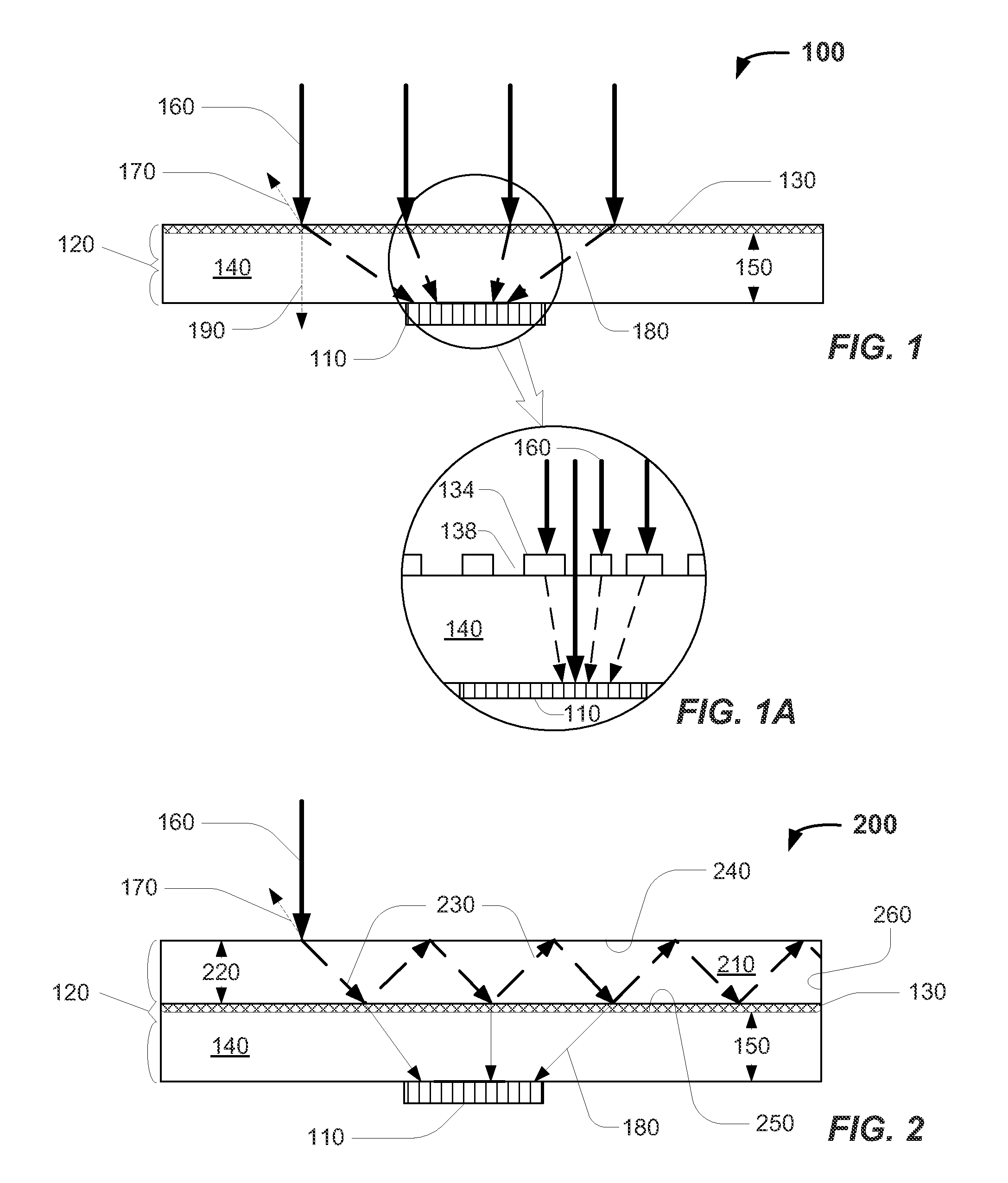
[0017]FIG. 1 depicts an elevation view of an exemplary energy collection system 100 according to one or more embodiments. FIG. 1A depicts an exploded view of an exemplary non-periodic, sub-wavelength, dielectric grating 130 disposed on the exemplary energy collection system 100 depicted in FIG. 1, according to one or more embodiments. The system 100 can include an energy collection device 110 and an energy concentration device 120 suitable for concentrating at least a portion of the incident electromagnetic radiation 160 onto at least a portion of the energy collection device 110.

[0018]The energy concentration device 120 can include, but is not limited to, a non-periodic, sub-wavelength, dielectric grating 130 and a substrate 140 having a thickness 150 disposed proximate at least a portion of the energy collection device 110. In one or more embodiments, a portion 170 of the incident electromagnetic energy 160 can be reflected by the non-periodic, sub-wavelength, dielectric grating 1...


PUM


Abstract

An energy collection system is provided. The system can include an energy collection device and an energy concentration device disposed proximate at least a portion of the energy collection device. The energy concentration device includes a non-periodic, sub-wavelength, dielectric grating.

Description

CROSS REFERENCES TO RELATED APPLICATIONS[0001]The present application is a related to prior, co-pending, PCT patent application Ser. No. PCT / US2009 / 051026, entitled “Non-Period Grating Reflectors with Focusing Power and Methods for Fabricating Same” invented by David Fattal, Jingjing Li, Raymond Beausoleil, and Marco Fiorentino, filed Jul. 17, 2009, owned by the same assignee now and at the time of invention, and such application is incorporated by reference as if fully set forth herein.BACKGROUND OF THE INVENTIONDescription of the Related Art[0002]Despite the vast potential energy source provided by the electromagnetic radiation released by the sun, efficient use of solar energy is hampered due to the diffuse nature of the energy received at the earth's surface. As such, facilities capable of converting the sun's electromagnetic radiation to electricity or other forms of energy on a commercial scale require significant real estate, thereby limiting the usefulness of the technology,...

Claims


Application Information

Patent Timeline
IPC IPC(8): H01L31/00
CPCG02B5/1809G02B6/4298H01L31/0547H01L31/0543Y02E10/52
Inventor PENG, ZHENFIORENTINO, MARCOFATTAL, DAVID A.QUITORIANO, NATHANIEL J.
Owner HEWLETT-PACKARD ENTERPRISE DEV LP
Why Eureka
Try Eureka