Eureka AIR delivers breakthrough ideas for toughest innovation challenges, trusted by R&D personnel around the world.

Tail-mounted pointable solar panels for solar-powered aircraft

Active Publication Date: 2011-04-14
AURORA FLIGHT SCI CORP
View PDF1 Cites 7 Cited by
  • Summary
  • Abstract
  • Description
  • Claims
  • Application Information

AI Technical Summary

Benefits of technology

[0015]The first tail component may comprise a first center of mass, the first center of mass being positioned along a roll pivot axis of the tail component about an aircraft fuselage. The second tail component may comprise a second center of mass, the second center of mass being positioned along the roll pivot axis of the second tail component about an aircraft fuselage. Each of the two surfaces of each of the first and second tail components may include a dihedral angle having a measure configured to ensure that the first and second centers of mass are positioned along the roll pivot axis of the respective tail component.
[0016]The first tail component may be pivotable about a first spanwise axis of the first tail component and configured to be rotated about the first spanwise axis such that a desired pitch control moment is caused. The second tail component may be pivotable about a second spanwise axis of the second tail component and configured to be rotated about the second spanwise axis such that a desired pitch control moment is caused. Each of the two surfaces of each of the first and second tail components may be offset from a boom portion of the aircraft to allow for free rotation of each tail component about the corresponding spanwise axis. Each respective spanwise axis may intersect a roll pivot axis of the tail component.
[0017]The first tail component may be pivotable about a first spanwise axis of the aircraft and configured to be rotated about the first spanwise axis such that a desired yaw control moment is caused. The second tail component may be pivotable about a second spanwise axis of the second tail component and configured to be rotated about the second spanwise axis such that a desired yaw control moment is caused. Each of th

Problems solved by technology

However, these horizontal panels are of little use for a solar powered aircraft that can operate at higher latitudes in the winter time, where the sun elevation angle may only be 10 to 20 degrees above horizontal, even at noon.
It is possible to place panels on the vertical tail of an aircraft, but this surface is of relatively small total area, and is ineffective at higher sun elevations.
However, while the size of a tail is much smaller than a wing, solar-powered aircraft tails may still be quite large.
This height would cause a very large penalty in mass and / or aerodynamic drag.
Thus, while prior art has shown the advantages of a sun tracking tail, there are major disadvantages arising from the large height of the tail during take off and landing.

Method used


Image

  • Tail-mounted pointable solar panels for solar-powered aircraft
  • Tail-mounted pointable solar panels for solar-powered aircraft
  • Tail-mounted pointable solar panels for solar-powered aircraft

Examples


Embodiment Construction

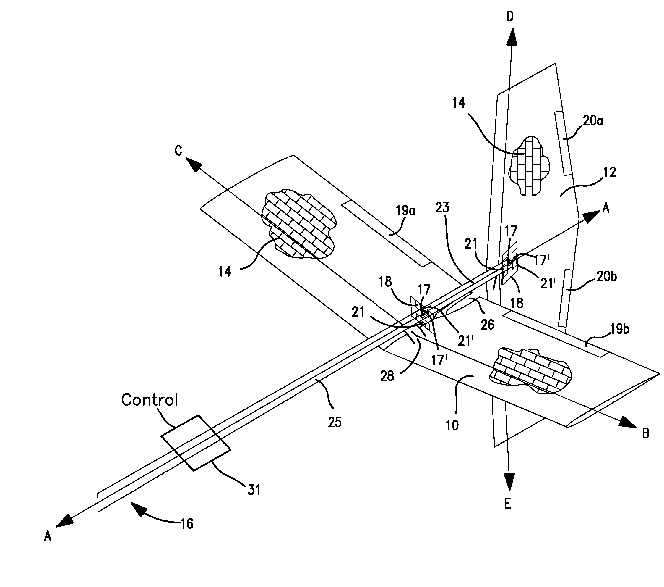
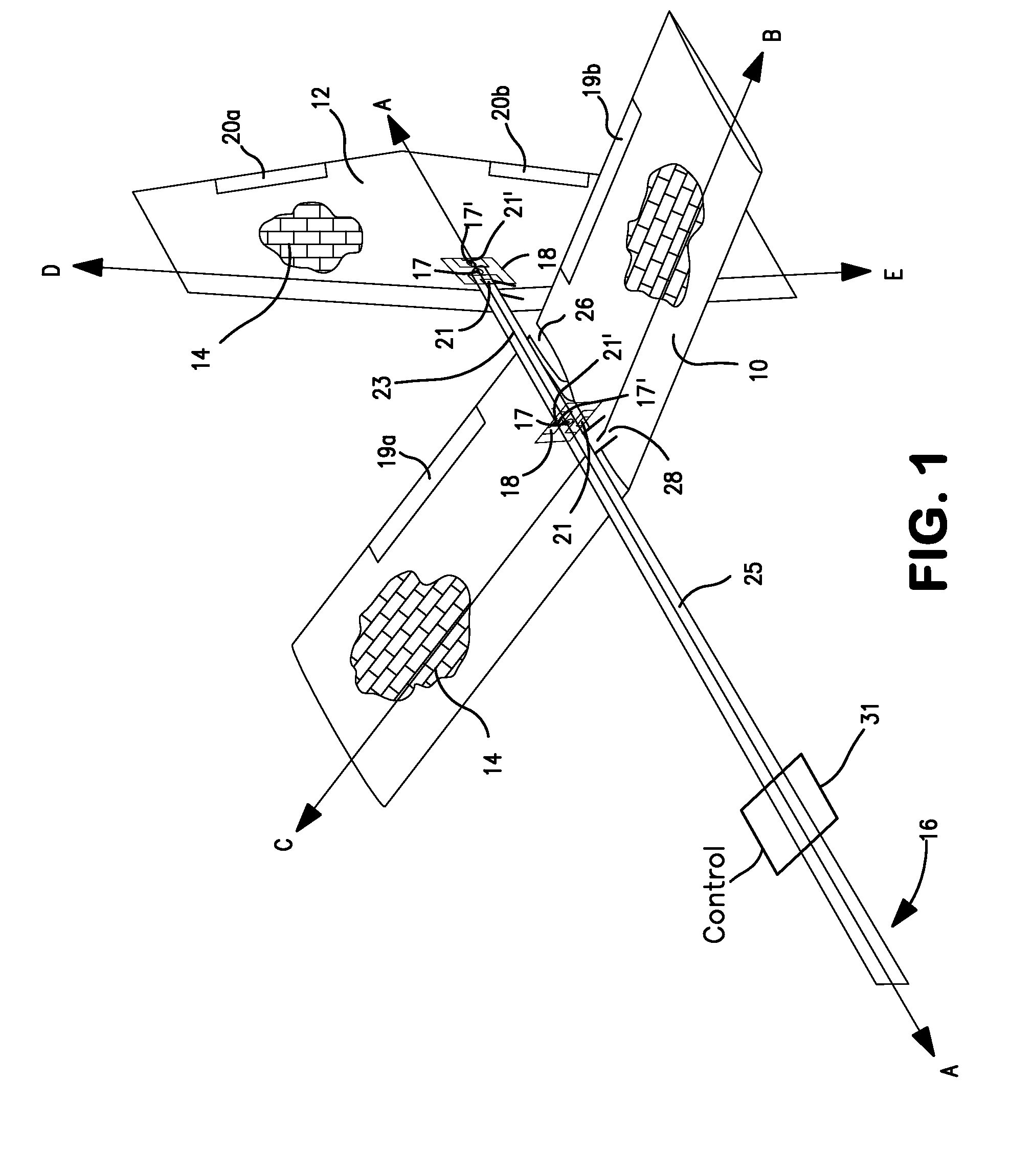
[0028]In a preferred embodiments of the present invention, instead of a unitary X-shaped tail assembly, the tail assembly is split into two or more separate tail components, with at least a first (front) tail component 10 preferably located fully in front of a second (rear) tail component 12. Preferably, in normal flight, the tail components 10, 12 are rotated about roll axis A to be substantially perpendicular to each other in the front view. For example, FIG. 1 depicts the tail assembly for night-flight or flight where the sun is directly overhead. The first tail component 10 is positioned as a traditional fixed-wing horizontal stabilizer, while the second tail component 12 is positioned as a traditional vertical stabilizer. The solar cells 14 on the first tail component 10 are positioned to capture solar energy.

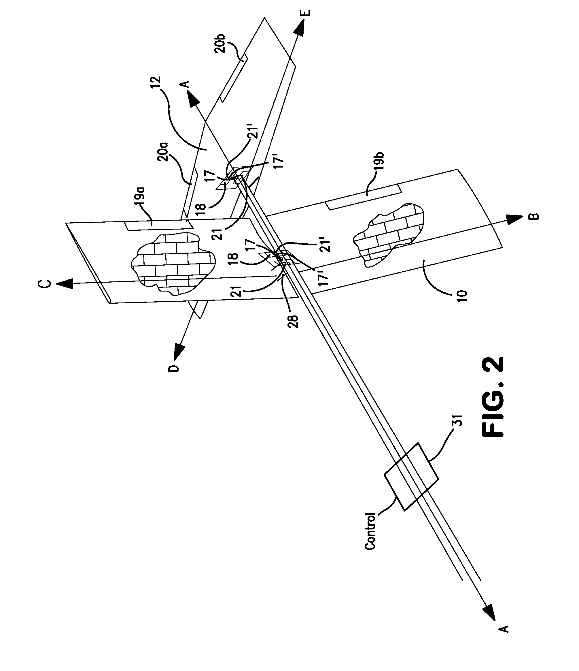
[0029]In FIG. 2, the front tail component 10 is rotated to a vertical position, to capture solar energy when the sun is on or near the horizon (or when the aircraft is in ...


PUM


Abstract

An aircraft tail section has a first tail component and a second tail component, the first tail component being positioned further forward than the second tail component with respect to a nose of the aircraft. Each tail component has two surfaces, each of the two surfaces of at least one of the first and second tail components comprises a solar panel configured to collect solar energy. Each tail component is rotatable with respect to a centerline of the aircraft such that an offset angle of between zero degrees and 180 degrees is formed between corresponding surfaces of the first and second tail components. Preferably, the tail components are rotated into (i) a takeoff and landing configuration that is substantially horizontal, and (ii) a crosswise configuration during flight such that collection of solar energy is maximized.

Description

[0001]This application claims priority to U.S. Patent Appln. No. 61 / 251,456, filed Oct. 14, 2009, the contents of which are incorporated herein by reference.[0002]The present invention was made with United States Government support under HR0011-08-C-0060, awarded by the Defense Advanced Research Projects Agency (DARPA). The U.S. Government has certain rights in the invention.BACKGROUND OF THE INVENTION[0003]1. Field of the Invention[0004]The present invention relates to solar-powered aircraft. More particularly, the present invention relates to configurations for arranging solar panels on a tail portion of an aircraft to optimize collection of solar energy to fully or partially power the aircraft.[0005]2. Related Art[0006]The advantages of pointable solar panels for solar-powered aircraft have long been recognized. While some configurations (e.g., NASA CR-3699) have panels separate from the normal stabilizing or lifting surfaces of the aircraft, there are weight and drag advantages ...

Claims


Application Information

Patent Timeline
IPC IPC(8): B64C1/00
CPCB64C2201/021B64C2201/042Y02T50/69B64D2211/00B64D27/24Y02T50/50B64U10/25B64U50/19B64U50/31B64D27/353
Inventor PARKS, ROBERT
Owner AURORA FLIGHT SCI CORP
Why Eureka
Eureka Blog
Learn More