Unlock instant, AI-driven research and patent intelligence for your innovation.

Edge rate control

a technology of edge rate and control, applied in the direction of pulse manipulation, electronic switching, pulse technique, etc., can solve the problem of interfering with the desired operation of the electronic devi

Active Publication Date: 2011-04-14
SEMICON COMPONENTS IND LLC
View PDF9 Cites 13 Cited by
  • Summary
  • Abstract
  • Description
  • Claims
  • Application Information

AI Technical Summary

Problems solved by technology

Currents generated in an electronic device from unanticipated electromagnetic energy can interfere with the desired operation of the electronic device.
Switched signals are often associated with generating a significant amount of EMI.

Method used


Image

  • Edge rate control
  • Edge rate control
  • Edge rate control

Examples


Embodiment Construction

The present inventor has recognized that controlling the transition rate, or the edge rate, of a switched signal can allow control of EMI emissions generated from conductors carrying the switched signal.

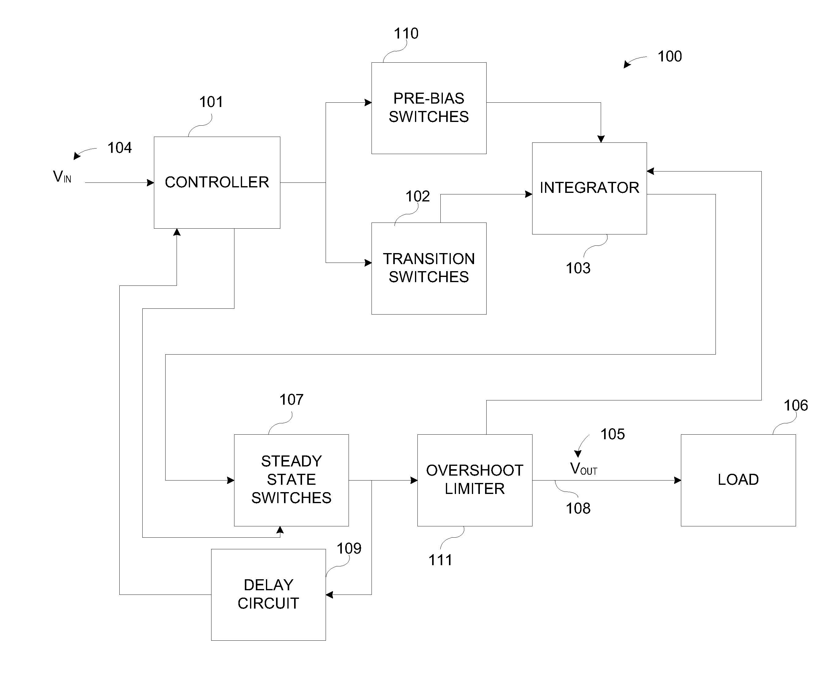
FIG. 1 illustrates generally a block diagram example of an edge rate control apparatus 100 configured to control an edge rate of an edge rate controlled, output signal (VOUT) 105 responsive to a switched input signal (VIN) 104. The edge rate control apparatus 100 can include a controller 101, transition switches 102, and an integrator 103 configured to provide the edge rate controlled, output signal (VOUT) 105 representative of a switched input signal (VIN) 104 (e.g., a switched input signal) to a load 106. In certain examples, the switched input signal 104 represents an audio signal, such as a switched audio signal from a Class-D amplifier, and the load 106 can include an audio output transducer, such as a speaker or ear phone, for example. It is understood that the switched input s...


PUM


Abstract

This document discusses, among other things, a system and method for reducing electromagnetic interference of a switched signal. In an example, a switched input signal can be received at an input and a transition rate of an edge rate controlled, switched output signal can be controlled in response to the received switched input signal.

Description

BACKGROUNDGenerally, a varying signal passing through a conductor can generate, and radiate, electromagnetic energy. Conductors can generate current when subjected to varying electromagnetic energy. Currents generated in an electronic device from unanticipated electromagnetic energy can interfere with the desired operation of the electronic device. Unanticipated electromagnetic energy is sometime referred to as electromagnetic interference (EMI). Standards have been formulated to encourage electronic device manufacturers to design products that limit the amount of EMI each product emits. Such standards, in turn, assist in providing minimum specifications for EMI a product should be able to withstand under normal operating conditions. Switched signals are often associated with generating a significant amount of EMI. In some devices, the faster a switched signal transitions from a first state to a second state, the stronger the radiated EMI.OVERVIEWThis document discusses, among other...

Claims


Application Information

Patent Timeline
IPC IPC(8): H03K5/1252
CPCH03K17/164
Inventor LLEWELLYN, WILLIAM D.
Owner SEMICON COMPONENTS IND LLC