
Variable range millimeter wave method and system

a millimeter wave and variable range technology, applied in the field of concealed object detection systems, can solve the problems of inability to provide adequate methods or systems that reduce the probability of incorrect composite image analysis, difficult to deploy long distance mmw optics in current operating ranges (generally below 100 ghz), and inability to accurately detect the presence of objects, etc., to save life and distance to react, eliminate legal concerns, and improve the effect of authenticating the presen

Inactive Publication Date: 2011-04-14
MICROSEMI
View PDF16 Cites 28 Cited by
  • Summary
  • Abstract
  • Description
  • Claims
  • Application Information

AI Technical Summary

Benefits of technology

[0015]One particular advantage provided by the embodiments of the variable range millimeter wave method and system is that long distance detection offers a new first line of defense to perimeter threats for the multitude of outdoor applications encountered by military, security and law enforcement personnel on a daily basis. A variable long-range threat detection system detects concealed threats that are still outside of the perimeter of the controlled area, providing life saving time and distance to react to and resolve a possible threat.
[0016]A variable range millimeter wave method and system fills a critical need to secure checkpoints, border crossings, compounds, large public gatherings, sporting events, visits of dignitaries and similar permanent or temporary indoor or outdoor situations. The system is also a valuable tool and resource to law enforcement for securing public areas, establishing probable cause for questioning, search and detention, securing crime scenes and riot scenes, as well as in response to credible intelligence of a threat to an unprotected or even secured location. The definitive, objective results of concealed object screening eliminate legal concerns raised by profiling and random sampling.
[0017]Another particular advantage provided by the embodiments of the variable range millimeter wave method and system is the ability to evaluate images from multiple sources in real time in order to better authenticate the presence of objects-of-interest in the images. Motion is detected in the scene by comparing multiple successive images so that the detection process is enabled or disabled based on the comparison results. In addition, an evaluation of multiple successive images can determine and calculate the relative motion of any objects-of-interest including direction, velocity and classification of motion (e.g., stationary, moving, rotating in place). The imagery of the visible spectrum camera and the millimeter wave camera convert the imagery into digital form and store the imagery in a computer memory device.
[0018]Another particular advantage provided by the embodiments of the variable range millimeter wave method and system is the ability to calculate the location and size of objects-of-interest in video images in real time and then automatically base further detection methodology according to the results. In addition, image processing can be altered based on the calculated results including early termination of further analysis, more detailed further analysis, or the use of different analysis methodology including differing inspection criteria, programs, algorithms, settings and sensitivities.
[0019]Another particular advantage provided by the embodiments of the variable range millimeter wave method and system is the ability to provide a means to selectively, automatically and intelligently indicate to subsequent computer software and algorithms the findings of the target's distance, direction and relative motion so that the subsequent computer software and algorithms can adaptively use differing inspection criteria, programs, algorithms, settings and sensitivities when evaluating the image (e.g., for threat detection, weapons detection, or detection of other objects).

Problems solved by technology

However, no adequate method or system has been provided that reduces the probability of incorrect composite image analysis caused by a target too far or close to from the millimeter wave or visible spectrum cameras.
However long distance and outdoor MMW deployments have been problematic.
Long distance MMW optics in current operating ranges (generally below 100 GHz) is challenging.
The relatively large wavelength of MMW at these frequencies causes the size of the optics to grow to unworkable size when trying to achieve reasonable resolution at a long standoff distance.
Atmospheric attenuation can degrade detector performance at certain frequencies.
Outdoor conditions of glint, glare, solar loading of emissive objects and the absolute cold temperature of the open sky in the MMW frequency band hamper and complicate existing imaging systems.

Method used


Image

  • Variable range millimeter wave method and system
  • Variable range millimeter wave method and system
  • Variable range millimeter wave method and system

Examples


Embodiment Construction

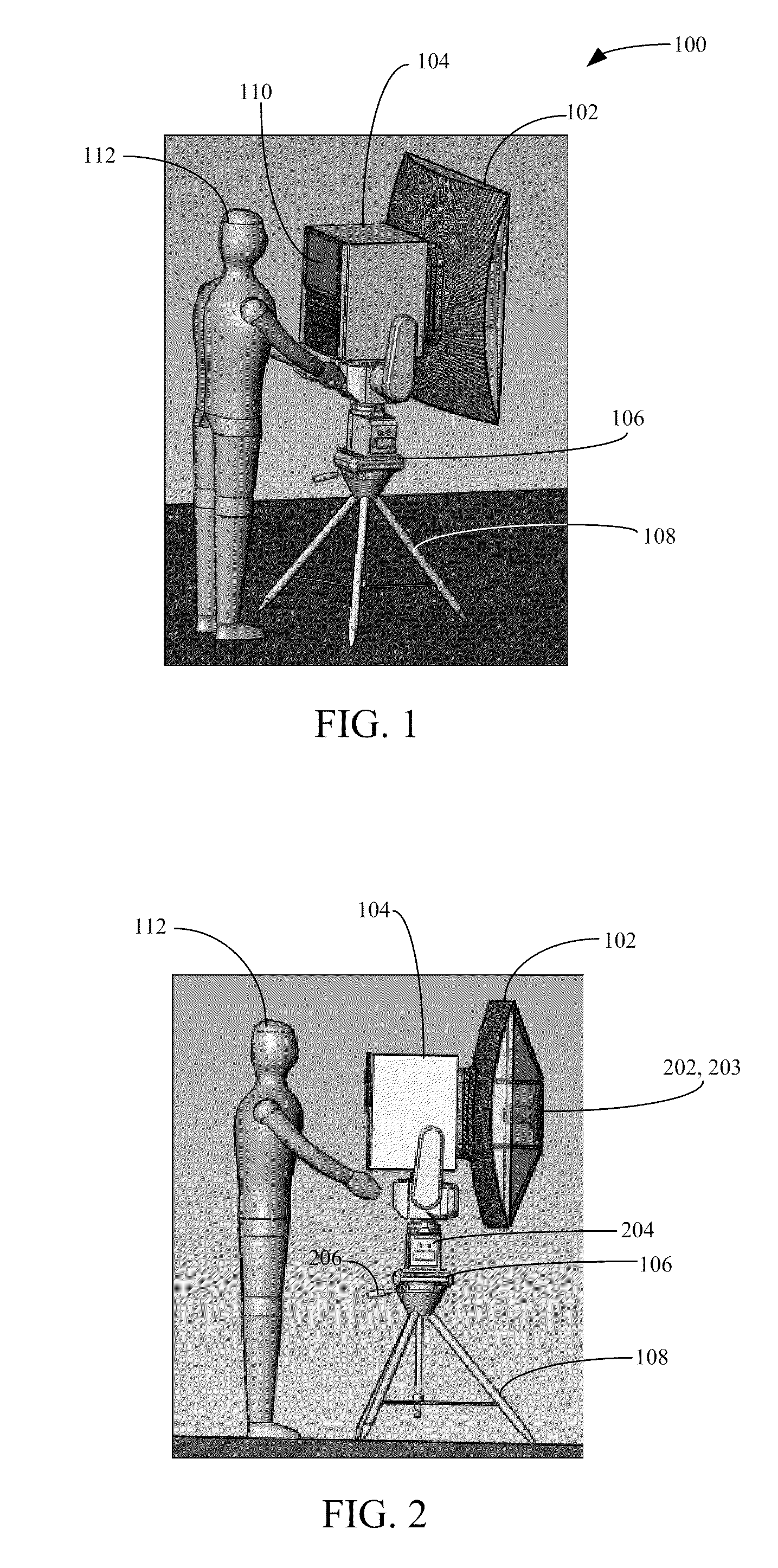
[0028]The variable range millimeter wave system may be transported by car, truck, tactical vehicle, or by aircraft. The system can be unloaded by hand, lift-truck, or ramp and moved into position on a site consisting of packed earth or sand, heavy gravel, concrete, etc. The system may be used indoors within any large building, air terminal, or lobby. In addition, the system may also be located outdoors under an open-sided shed, tent, or canopy to provide shelter from the elements for equipment and operators. Impact attenuators, sandbags, and other personnel protection measures can be positioned around the unit as required. A suitable location will include a direct line-of-site to one or more areas of interest. Electricity may be provided from local power lines, generators, battery arrays, or from a truck or other vehicle. The system may be self-contained and set-up time is approximately 15 minutes. Training time for an operator is approximately two to four hours. One operator is req...


PUM


Abstract

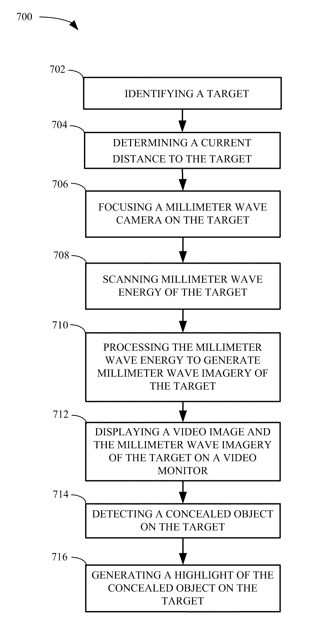
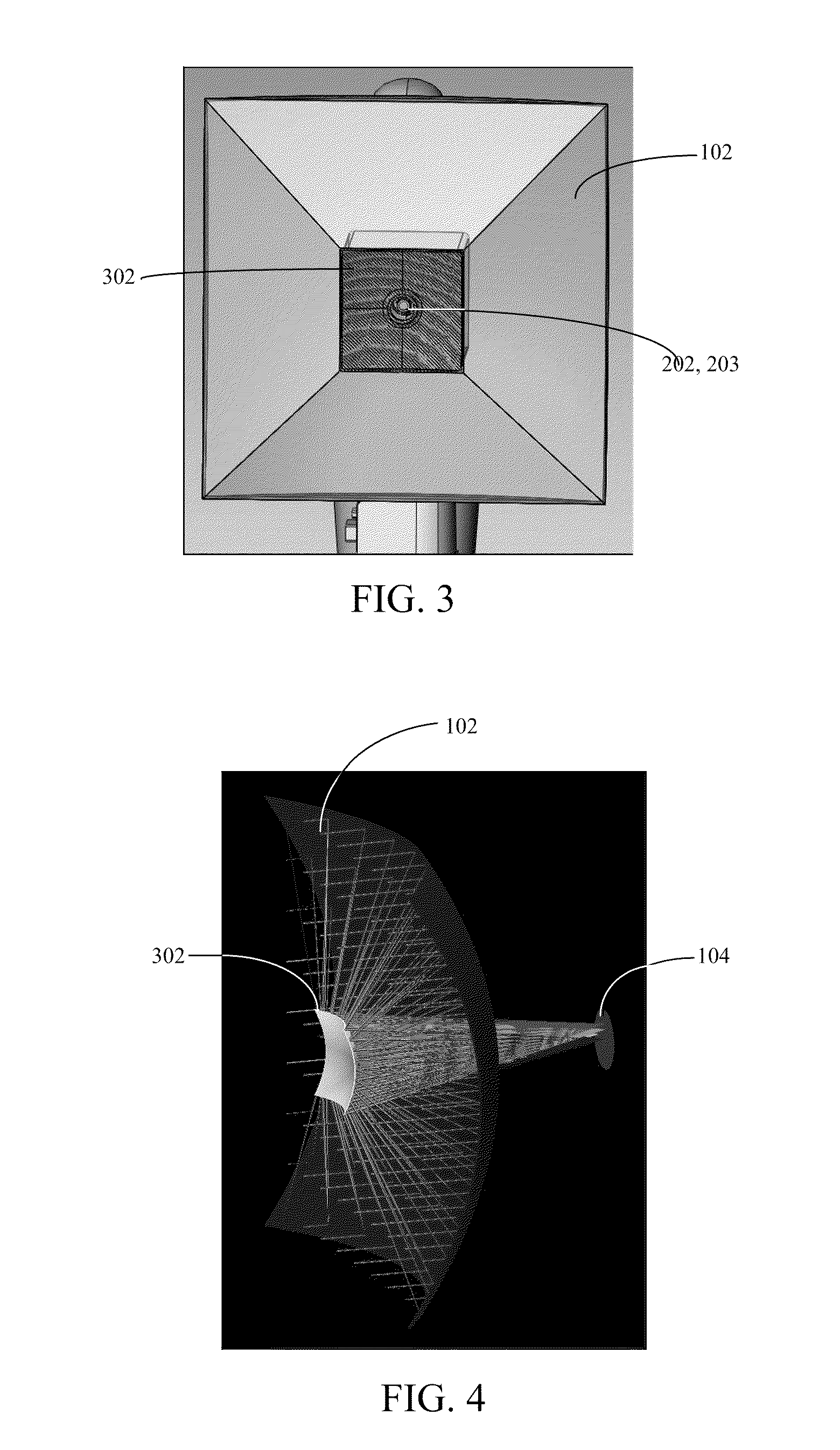
A variable range millimeter wave method and system is disclosed. In a particular embodiment, the system includes a primary mirror having an aperture to reflect millimeter wave energy to a secondary mirror, where the secondary mirror is disposed in front of the primary mirror and adapted to redirect the millimeter wave energy to a millimeter wave sensor / detector of a millimeter wave camera. The millimeter wave camera is configured to process the millimeter wave energy to visually detect concealed objects hidden on a target and an operating frequency of the millimeter wave camera is between 225 GHz and 275 GHz. In addition, the system includes a laser rangefinder, GPS and altimeter to determine a location of the target and to optimize a focus of the millimeter wave camera. A video monitor displays millimeter wave imagery and video images spatially and temporally relative to the millimeter wave imagery to aid targeting.

Description

I. FIELD[0001]The present invention relates in general to the field of concealed object detection systems using millimeter wave imagery, and in particular to a variable range millimeter wave method and system.II. DESCRIPTION OF RELATED ART[0002]A passive millimeter wave camera has the ability to detect and image objects hidden under clothing using millimeter wave imagery. The passive millimeter wave camera detects radiation that is given off by all objects. The technology works by contrasting the millimeter wave signature of the human body, which is warm and reflective, against that of a gun, knife or other contraband. Those objects appear darker or lighter because of the differences in temperature, hence, millimeter wave energy, between the human body and the inanimate objects.[0003]An object-based scene is generated for viewing on a video monitor with individual objects having spatial and temporal relationships. The objects may be created in any number of ways, including signals f...

Claims


Application Information

Patent Timeline
IPC IPC(8): G01S13/88G01S13/00G01S13/08
CPCG01S7/03G01S7/415G01S13/89G01S13/865G01S13/887G01S13/42
Inventor DALY, ROBERT PATRICKSMALL, FARRELL ANTHONYDREWES, JONATHAN JENSEN
Owner MICROSEMI
Learn More