
Inkjet recording apparatus and method, and abnormal nozzle detection method

a recording apparatus and nozzle technology, applied in the direction of printing, inking apparatus, other printing apparatus, etc., can solve the problems of increased waste of paper, non-uniformity and density non-uniformities, and ejection defects with a certain probability, so as to improve throughput and accuracy. high, the effect of high reliability

Inactive Publication Date: 2011-04-14
FUJIFILM CORP
View PDF4 Cites 56 Cited by
  • Summary
  • Abstract
  • Description
  • Claims
  • Application Information

AI Technical Summary

Benefits of technology

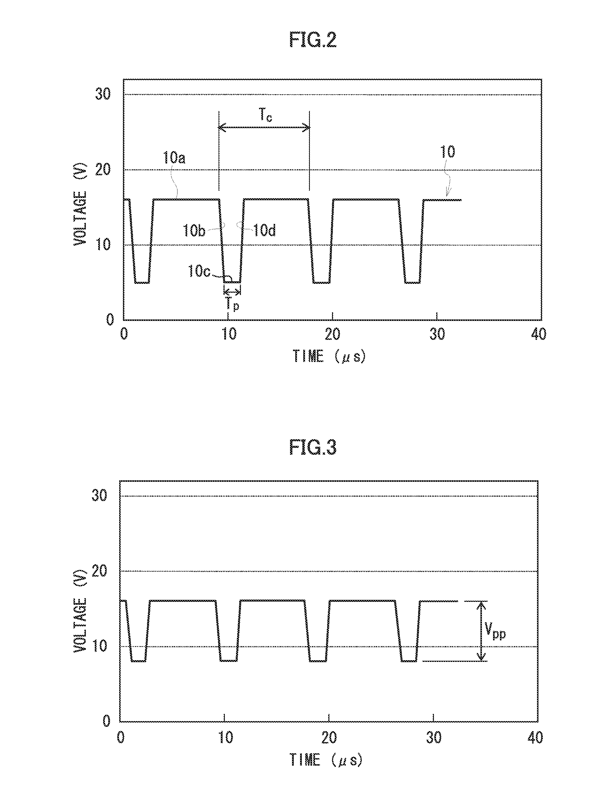
The present invention provides an inkjet recording apparatus and method that can detect abnormal nozzles in a timely manner and prevent image defects caused by ejection abnormalities. By using an abnormal nozzle detective waveform that reduces ejection velocity compared to the recording waveform, the ejection force during the detection process is weaker, allowing for better detection of abnormal nozzles. This results in improved recording stability and reduced paper waste. Additionally, the invention allows for the detection of abnormal nozzles at the head position where deposition of droplets is possible, without withdrawing the inkjet head to a maintenance position, and avoids reduction in throughput. The invention also provides a method for forming test patterns for abnormal nozzle detection and density non-uniformity correction, and a device for controlling the ejection of droplets from the nozzles.

Problems solved by technology

However, in recording by an inkjet method, ejection defects occur with a certain probability in nozzles of the inkjet head, and stripe non-uniformities and density non-uniformities occur in recorded images at positions corresponding to the defective nozzles.
These ejection defects which lead to decline in image quality produce an increase in wasted paper and give rise to a decline in throughput due to the carrying out of head maintenance.
In particular, in a single-pass method which performs image formation by means of one recording scan, even an ejection defect in one nozzle has a great effect on the overall image quality.
Moreover, in the case of a single-pass method which emphasizes productivity, since the inkjet head is always positioned above recording media, then it is difficult to carry out head maintenance during the image formation operation.
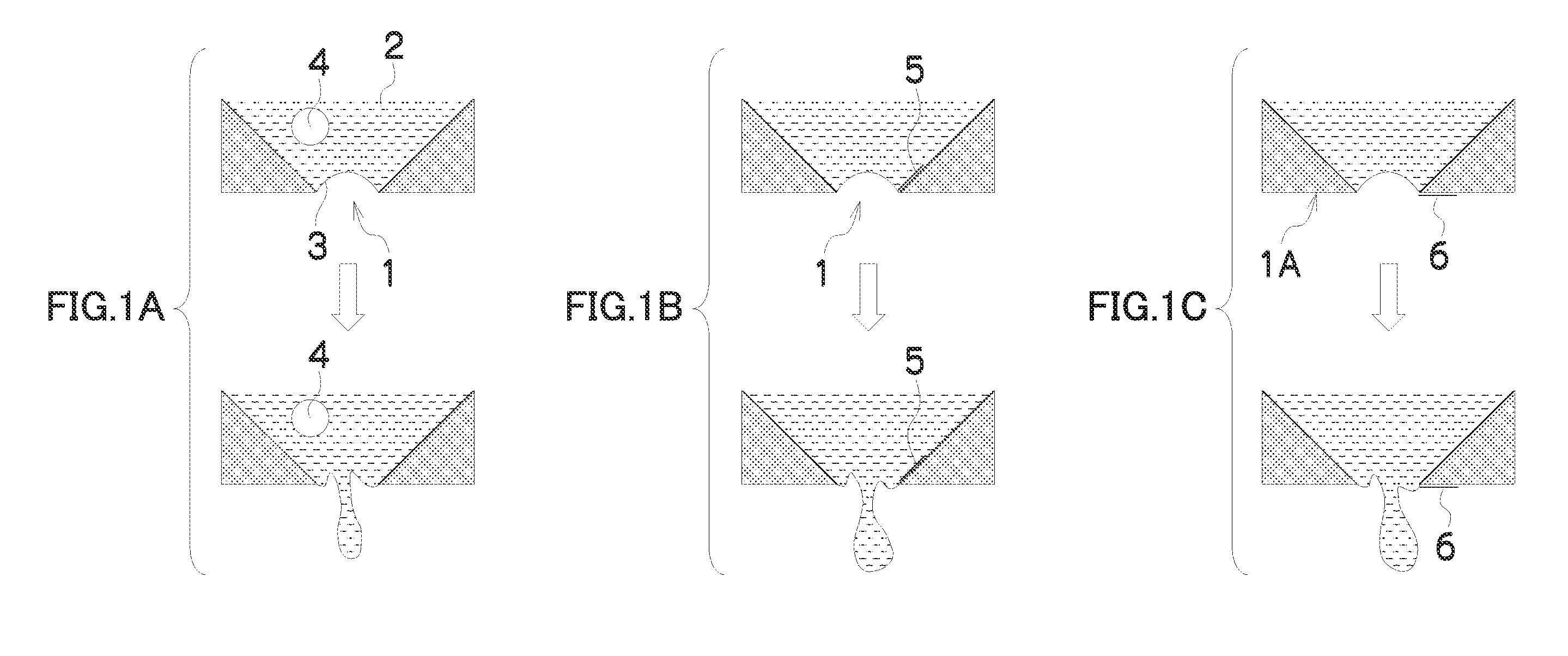
Possible causes of the occurrence of ejection defects in the inkjet heads include: decline in ejection force due to bubbles which have entered into the nozzles, adherence of foreign matter to the vicinity of the nozzles, abnormality in the liquid-repelling properties in the vicinity of the nozzles, abnormality in the nozzle shapes, and the like.
Moreover, a nozzle that has produced an ejection defect is liable to create an ink mist due to instable ejection, and this mist causes deterioration of the surrounding nozzles which are normally functioning.
However, it is difficult to completely prevent ejection defects.
However, this technology has a problem in that throughput declines due to adopting a composition in which the print head is moved to the maintenance position outside the image formation region, and the ejection failure nozzle detection and the maintenance are carried out at the maintenance position.
Moreover, it is silent about detection of ejection defects (e.g., flight deviation and splashing) other than ejection failures, and the actual waveform used for detection is not made clear.
However, in order to detect perceivable ejection abnormalities, the technology requires an expensive detective device, such as a high-resolution imaging device (e.g., CCD) capable of accurately determining the deposition of ink droplets or a device capable of measuring the state of flight of ink droplets, or the like; it also takes time for the detection process.
Moreover, since it is not possible to detect abnormalities during image formation with this technology, then throughput declines.
As stated above, it has been difficult to achieve both recording stability and throughput in the related art.

Method used


Image

  • Inkjet recording apparatus and method, and abnormal nozzle detection method
  • Inkjet recording apparatus and method, and abnormal nozzle detection method
  • Inkjet recording apparatus and method, and abnormal nozzle detection method

Examples


embodiment 1

Flowchart of Non-Uniformity Correction Sequence (Embodiment 1)

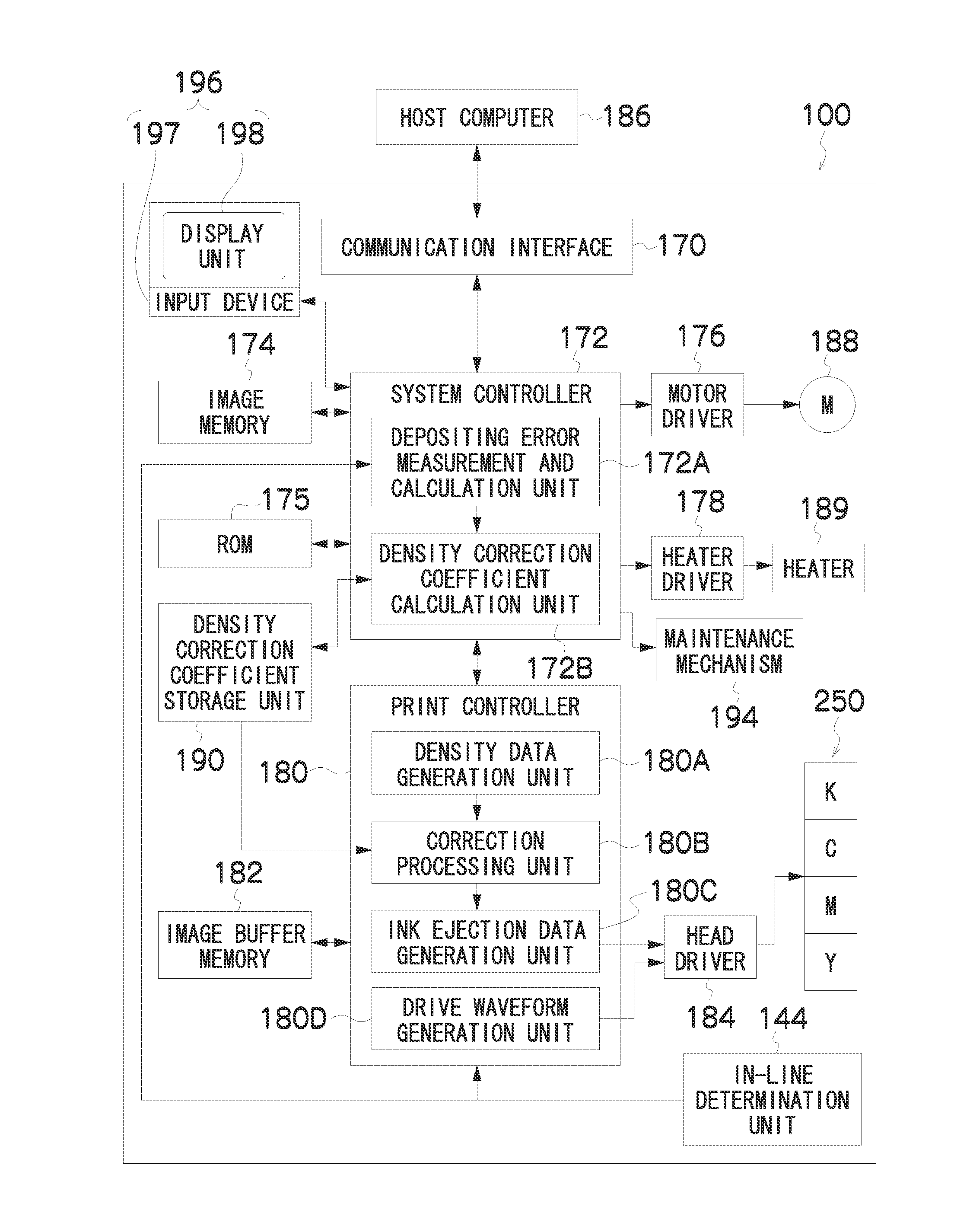
[0234]FIG. 19 is a flowchart showing a non-uniformity correction sequence in the inkjet recording apparatus 100 according to an embodiment of the present invention. The non-uniformity correction according to the present embodiment combines: an advance correction step (step S11) of acquiring correction data by measuring a test chart by means of the sensor (the in-line determination unit 144) inside the inkjet recording apparatus 100, before the start of continuous printing for a print job; and on-line correction steps (steps S20 to S38) for carrying out correction in an adaptive fashion while carrying out continuous printing (without interrupting printing), by measuring a test chart with the in-line determination unit 144 during continuous printing.

[0235]In the advance correction step (step S11), advance ejection defect detection processing is carried out in parallel with advance non-uniformity correction processing.

[0236]...

embodiment 2

Flowchart of Non-Uniformity Correction Sequence (Embodiment 2)

[0298]FIG. 28 is a flowchart showing a second embodiment of a non-uniformity correction sequence in the inkjet recording apparatus 100 according to an embodiment of the present invention. In FIG. 28, steps which are the same as or similar to those in the flowchart shown in FIG. 19 are denoted with the same step numbers and description thereof is omitted here.

[0299]The non-uniformity correction sequence shown in FIG. 28 performs advance correction off-line, instead of the advance correction using the in-line determination unit shown in FIG. 19. More specifically, the non-uniformity correction shown in FIG. 28 combines: advance correction (off-line correction) steps (steps S12 to S16) of acquiring correction data by measuring a test chart off-line before the start of continuous printing for a print job; and on-line correction steps (steps S20 to S40) for carrying out correction in an adaptive fashion while carrying out cont...


PUM


Abstract

The inkjet recording apparatus includes: an abnormal nozzle detective waveform signal generating device which generates a drive signal having an abnormal nozzle detective waveform including a waveform that is different from a recording waveform and applied to pressure generating elements when performing ejection for abnormality detection to detect an abnormal nozzle among nozzles; an abnormal nozzle detective device which identifies the abnormal nozzle showing an ejection abnormality from results of the ejection for abnormality detection; a correction control device which corrects image data in such a manner that ejection is stopped from the identified abnormal nozzle and a desired image is recorded by the nozzles other than the abnormal nozzle; and a recording ejection control device which performs image recording by controlling ejection from the nozzles other than the abnormal nozzle in accordance with the image data that has been corrected by the correction control device.

Description

BACKGROUND OF THE INVENTION[0001]1. Field of the Invention[0002]The present invention relates to an inkjet recording apparatus and method, and an abnormal nozzle detection method, and in particular to technology for detecting ejection defects (flight deviation of ejected droplets, volume abnormality of ejected droplets, splashing, ejection failure, and the like) occurring in an inkjet head having a plurality of nozzles (droplet ejection ports), and to correction technology for suppressing decline in image quality arising from nozzles having abnormalities.[0003]2. Description of the Related Art[0004]An inkjet apparatus forms images by ejecting and depositing a functional material (hereinafter, taken to be synonymous with “ink”) using an inkjet head, and has characteristic features which include: excellent eco-friendly properties, capability for high-speed recording on various different recording media, the capability to achieve high-definition images which are not liable to bleeding....

Claims


Application Information

Patent Timeline
Patent Type & Authority Applications(United States)
IPC IPC(8): B41J29/38
CPCB41J2/0451B41J2/04581B41J2/04588B41J2/04596B41J2/04598B41J2/14233B41J2/2146B41J2/16579B41J2/2139B41J2/2142B41J2002/14459B41J2202/20B41J2/155
Inventor HIRATO, KATSUYUKINISHIKAWA, BAN
Owner FUJIFILM CORP
Learn More