Method for Calculating a Customized Progressive Addition Surface; Method for Manufacturing a Progressive Addition Lens

Active Publication Date: 2011-04-14
ESSILOR INT CIE GEN DOPTIQUE
View PDF4 Cites 4 Cited by
  • Summary
  • Abstract
  • Description
  • Claims
  • Application Information

AI Technical Summary

Benefits of technology

[0008]Accordingly, it would be a significant advantage if a progressive addition lens design was able to be dispensed to a wearer such that the selected progressive addition lens design had a suitable peripheral design a

Problems solved by technology

However, although the selected progressive addition lens may have a peripheral design which is suitable for the wearer, other features, such as the inset, the corridor length, also called length of progression, may not be optimal for the wearer's visual requirements or non compatible with the wearer's spectacle frame.
Indeed, in a selection method which involves selecting a particular progressive addition lens surface design from a range of progressive addition lens designs, a progressive addition lens design having a suitable peripheral design together with other design features, such as the inset, the corridor length, which are related to the requirements of the wearer may not be available.

Method used


Image

  • Method for Calculating a Customized Progressive Addition Surface; Method for Manufacturing a Progressive Addition Lens
  • Method for Calculating a Customized Progressive Addition Surface; Method for Manufacturing a Progressive Addition Lens
  • Method for Calculating a Customized Progressive Addition Surface; Method for Manufacturing a Progressive Addition Lens

Examples


examples of embodiments

Where N>1

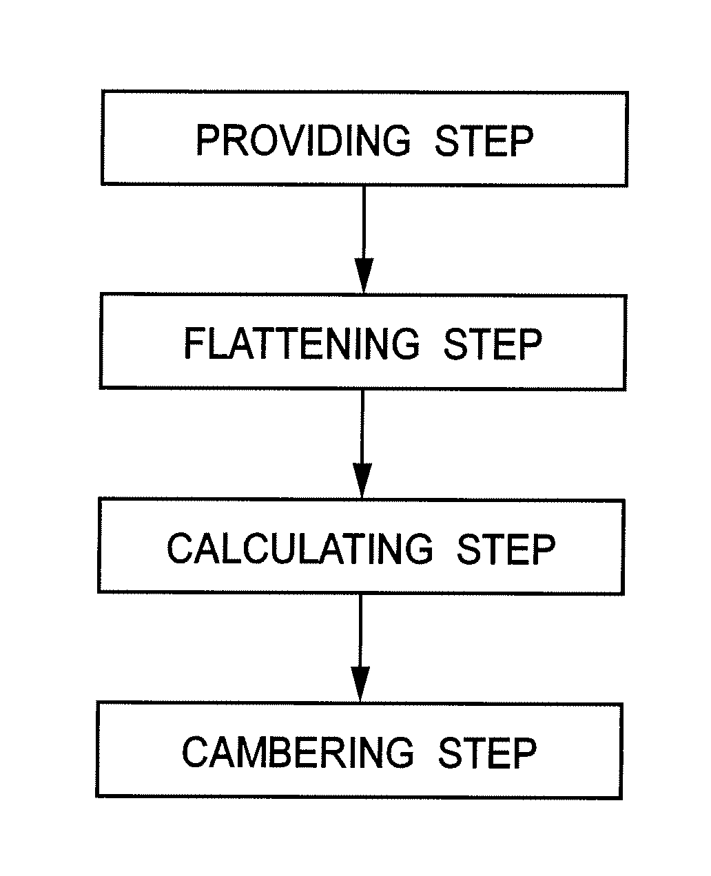
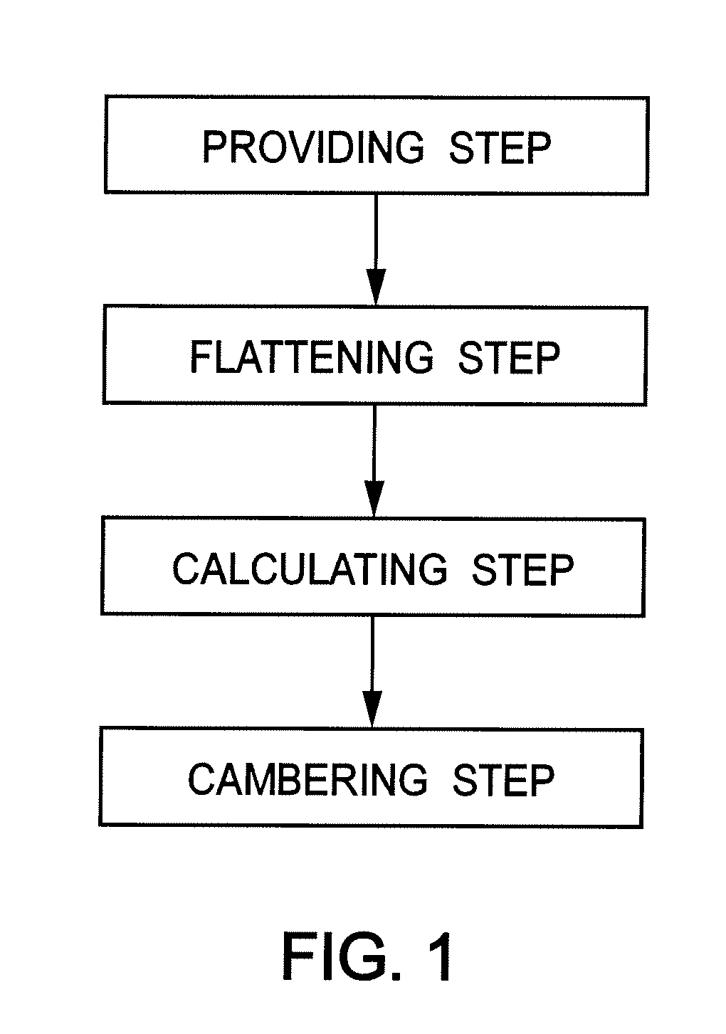
[0135]According to an embodiment of the invention, the providing step a) may comprise providing N initial progressive addition surfaces with N>1, and the scaling parameters εk may be chosen as equal to 1 for all the surfaces.

[0136]According to such embodiment, the N initial progressive addition surfaces are flattened according to step b) of a method according to the invention.

[0137]According to such embodiment, the isotropic function TPk,r;1 used during the calculation step c), is the identity function. Therefore, the calculation step c) consists in calculating a transformed intermediate surface S″ by applying

S″(Pi)=∑k=1NαkSk′(Pi,k),

where αk is a coefficient specific to each intermediate surface S′k.

[0138]The cambering step d) can be carried out as described previously.

[0139]Advantageously such embodiment of the invention may be used to customize a surface design for a customized progressive addition surface. Indeed, the linear combination of given surface designs may be us...

example

[0141]The invention may be illustrated by the following example.

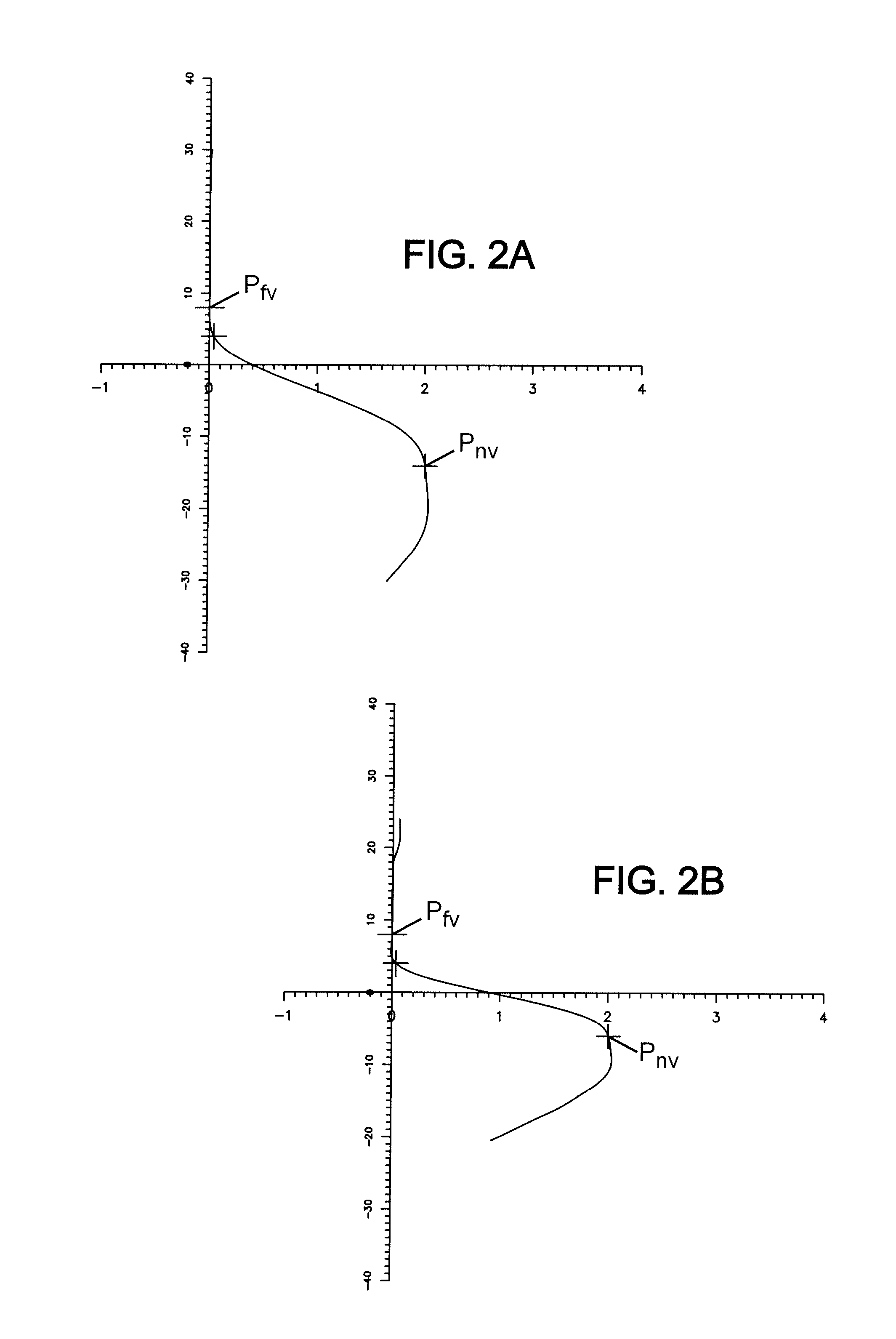
[0142]In this example, the method according to the invention has been applied to a single initial progressive addition surface referenced “confort orma, base 5.50, addition 2.2, optical index n=1.502, the coordinates of the near vision point being (2.5, −14) mm and the coordinates of the far vision point being (0,8) mm.”

[0143]In this example, the points Pi of the initial progressive addition surface are expressed in a Cartesian coordinate system whose origin is the optical centre of the initial progressive addition surface. The x-axis is selected so has to have the optical centre and the far vision point on the x-axis.

[0144]The points Pi of the initial progressive addition surface are provided with the sampling interval of 2 mm over the full surface.

[0145]The near vision point of the initial addition surface has its y-coordinate equal to −14mm.

[0146]In this example, the inventors have customized the y-coordinates of the...


PUM


Abstract

A method for calculating a customized progressive addition surface S′″ of a progressive addition lens (PAL) made of a material having an optical index of n, the method, comprising at least the successive steps of: a) providing N initial progressive addition surfaces where N≧1, b) calculating N intermediate surfaces S′k by flattening each initial progressive addition surfaces Sk, c) calculating a transformed intermediate surface S″, d) calculating the customized progressive addition surface S′″ by cambering the transformed intermediate surface S″.

Description

RELATED APPLICATIONS[0001]This is a U.S. national stage of application No. PCT / EP2009 / 057246, filed on Jun. 11, 2009.[0002]This application claims the priority of European application no. 08305250.6 filed Jun. 12, 2008, the entire content of which is hereby incorporated by reference.FIELD OF THE INVENTION[0003]The invention relates to a process for calculating a customized progressive addition surface of a progressive addition lens (PAL), and to a manufacturing method of a progressive addition lens customized using the method according to the invention.BACKGROUND OF THE INVENTION[0004]Conventional progressive addition lenses are lenses which have a far vision zone, a near vision zone, and a progressive corridor (or channel) there between. The progressive corridor provides a gradual power progression from the far vision zone to the near vision zone without dividing line or prismatic jump.[0005]Generally, the dispensing of a particular progressive addition lens to a wearer involves se...

Claims


Application Information

Patent Timeline
IPC IPC(8): G02C7/02
CPCG02C7/024G02C7/063G02C7/028
Inventor ALLIONE, PASCAL
Owner ESSILOR INT CIE GEN DOPTIQUE
Why Eureka
Try Eureka