Method and device for monitoring WDM signal light

a technology of signal light and transmission device, which is applied in the direction of transmission monitoring, electromagnetic repeaters, multiplex communication, etc., can solve the problems that the wdm transmission device described above cannot effectively perform signal light monitoring, optical signals, and signal light monitoring with high precision cannot be realized, and achieve high precision and high reliability

Inactive Publication Date: 2011-04-14
NEC CORP
View PDF37 Cites 6 Cited by
  • Summary
  • Abstract
  • Description
  • Claims
  • Application Information

AI Technical Summary

Benefits of technology

[0010]Accordingly, an object of the present invention is to provide a method and device for monitoring WDM signal light in a WDM transmission device that can achieve signal light monitoring with high precision and high reliability.
[0014]According to the present invention, it is possible to realize signal light monitoring with high precision and high reliability.

Problems solved by technology

However, the WDM transmission devices as described above cannot effectively perform signal light monitoring when an abnormality (or fault) occurs in a route between the input port of the WDM transmission device and the input of the monitoring means.
For example, in both of the cases where an optical signal actually does not exist and where an abnormality has occurred in the route, the optical signal cannot be detected and therefore the monitoring means issues the same alarm.
Hence, signal light monitoring with high precision cannot be realized.
Moreover, the WDM transmission devices as described above cannot monitor an optical signal for a fault when an abnormality occurs in the device's monitoring means itself.
Such a situation results in degraded reliability.

Method used


Image

  • Method and device for monitoring WDM signal light
  • Method and device for monitoring WDM signal light
  • Method and device for monitoring WDM signal light

Examples


first exemplary embodiment

1. First Exemplary Embodiment

1.1) WDM Transmission Device

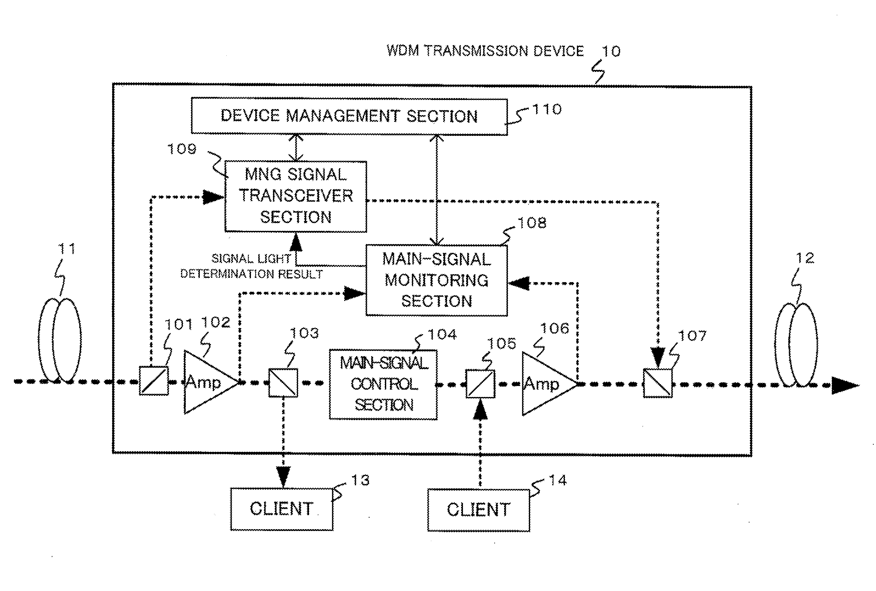
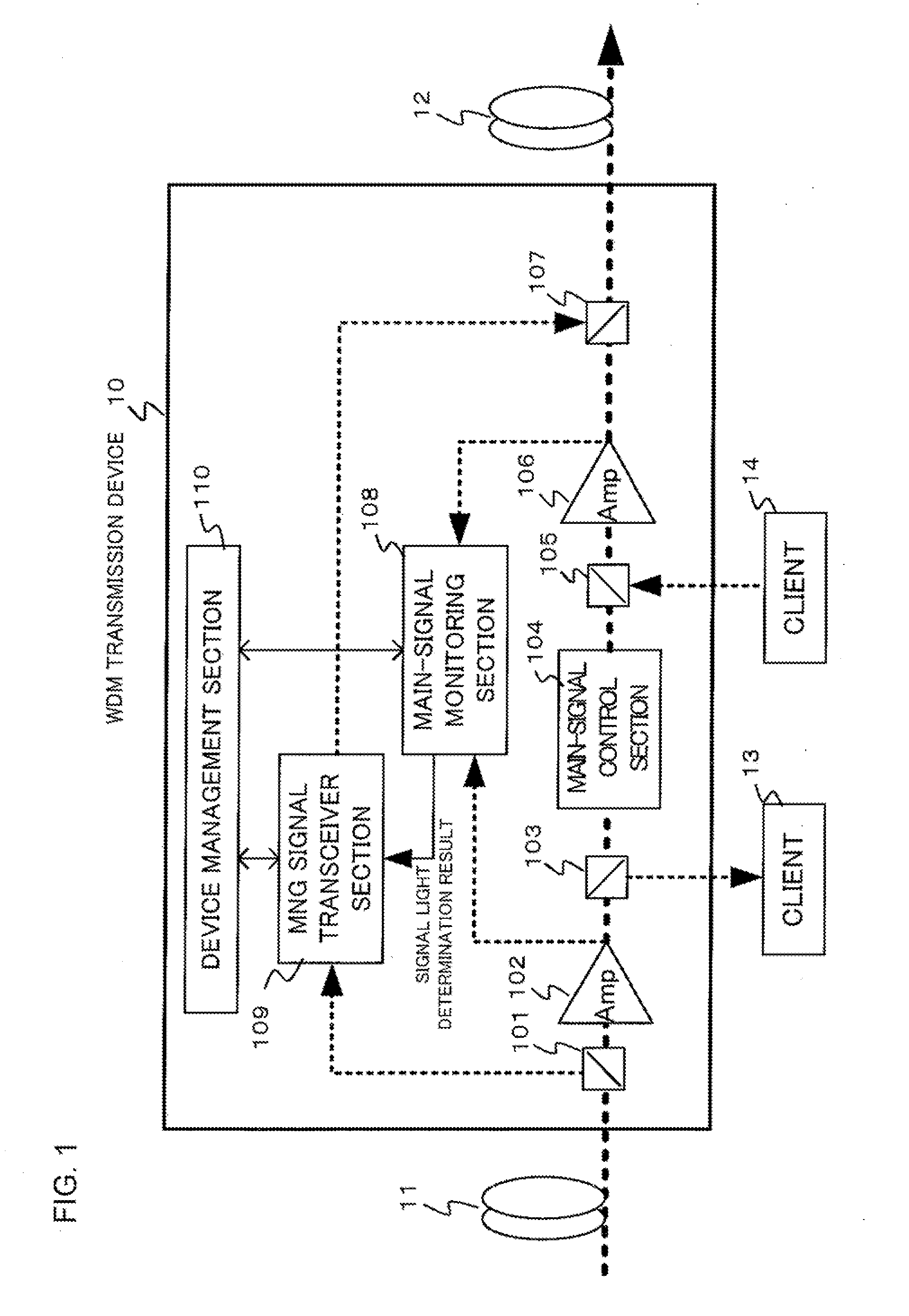
[0022]Referring to FIG. 1, a WDM transmission device 10 is connected to an upstream WDM transmission device through an optical transmission line 11 and to a downstream WDM transmission device through an optical transmission line 12. The optical transmission lines 11 and 12 are optical fiber cable. Moreover, it is assumed that the WDM transmission device 10 has an ADM function of dropping an optical signal of a predetermined wavelength to output it to a client 13 and adding an optical signal of a predetermined wavelength inputted from a client 14 for transmission. Further, it is assumed hereinafter that main signal light of WDM signal light uses the C-Band or L-Band and management signal light, which will be described later, uses an arbitrary wavelength band where no interference occurs with the main signal light.

[0023]The WDM signal light received through the optical transmission line 11 passes through an optical splitting sec...

second exemplary embodiment

2. Second Exemplary Embodiment

[0046]The basic configuration of a WDM transmission device according to a second exemplary embodiment of the present invention is similar to that of the first exemplary embodiment described above. The different point is that a plurality of inputs are made to the main-signal control section and level equalization is performed after a wavelength is selected in the device. It is possible to obtain effects similar to those of the first exemplary embodiment even when the present invention is applied to such a WDM transmission device that outputs WDM signal light through wavelength selection from a plurality of WDM signal light inputs. Hereinafter, a description will be given of the case, as an example, where a device has two input systems.

[0047]Referring to FIG. 6, it is assumed that a WDM transmission device 60 is connected to two upstream WDM transmission devices through optical transmission lines 11 and 15 respectively and connected to a downstream WDM tr...


PUM


Abstract

A WDM signal light monitoring device includes a first monitor for monitoring input-side WDM main signal light and output-side WDM main signal light for each wavelength; and a second monitor for monitoring the first monitor by comparing a monitoring result received from an upstream WDM transmission device with a monitoring result of the first monitor, wherein the monitoring result of the first monitor is transmitted to a downstream WDM transmission device in the system.

Description

[0001]This application is based upon and claims the benefit of priority from Japanese Patent Application No. 2009-235985, filed on Oct. 13, 2009, the disclosure of which is incorporated herein in its entirety by reference.BACKGROUND OF THE INVENTION[0002]1. Field of the Invention[0003]The present invention relates to an optical transmission system using wavelength division multiplexing (WDM) and a WDM transmission device such as an optical node or optical repeater used in the optical transmission system and, more particularly, to a WDM transmission device having signal light monitoring functionality and a signal light monitoring method for the device.[0004]2. Description of the Related Art[0005]In WDM optical transmission systems using the technologies of multiplexing a plurality of optical signals of different wavelengths onto a single optical fiber, various add-drop multiplexers (ADM) and optical repeaters having signal light monitoring functionality have been proposed.[0006]For e...

Claims


Application Information

Patent Timeline
Patent Type & Authority Applications(United States)
IPC IPC(8): H04B17/00H04B10/07H04B10/077H04B10/079H04B10/29H04B10/291H04J14/00H04J14/02
CPCH04J14/0221H04B10/0775
Inventor KIKUCHI, BAKU
Owner NEC CORP
Why Eureka
Try Eureka