Power transmitting device and vehicle having same mounted thereon

a technology of power transmission device and transmission device, which is applied in the direction of clutches, mechanical devices, gearing, etc., can solve the problem of increasing the overall size of the devi

Active Publication Date: 2011-04-21
AISIN AW CO LTD
View PDF11 Cites 18 Cited by
  • Summary
  • Abstract
  • Description
  • Claims
  • Application Information

AI Technical Summary

Benefits of technology

[0015]The vehicle of the present invention is installed with the power transmission device of the present invention of any of the modes described above. Therefore, effects achieved by the power transmission of the present invention, for example, an effect of suppressing momentary drops in

Problems solved by technology

However, the relatively high pressure-feeding capability required of the electric oil pump enlarg

Method used


Image

  • Power transmitting device and vehicle having same mounted thereon
  • Power transmitting device and vehicle having same mounted thereon
  • Power transmitting device and vehicle having same mounted thereon

Examples


Embodiment Construction

[0028]Next, an embodiment will be used to describe a best mode for carrying out the present invention.

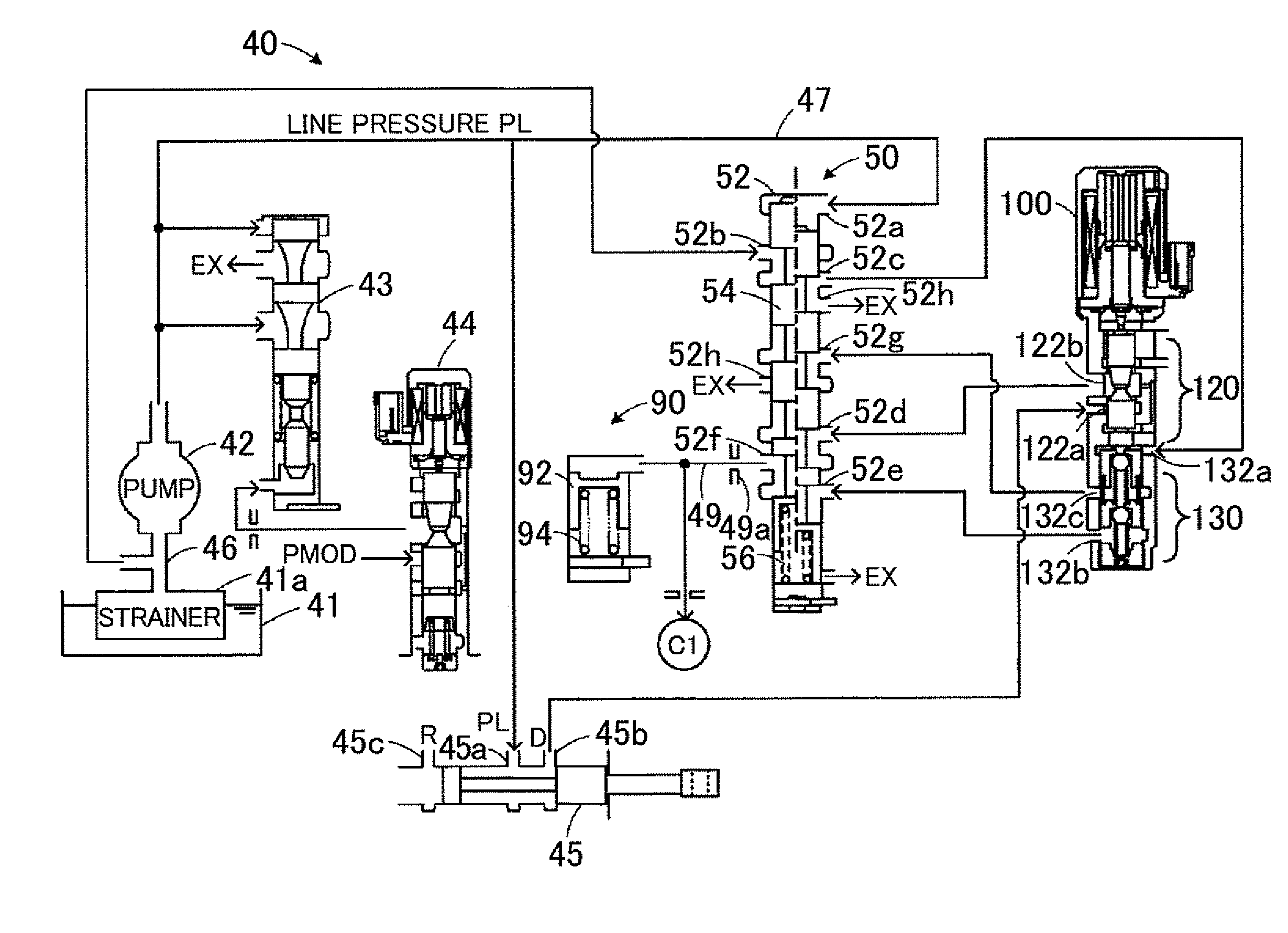
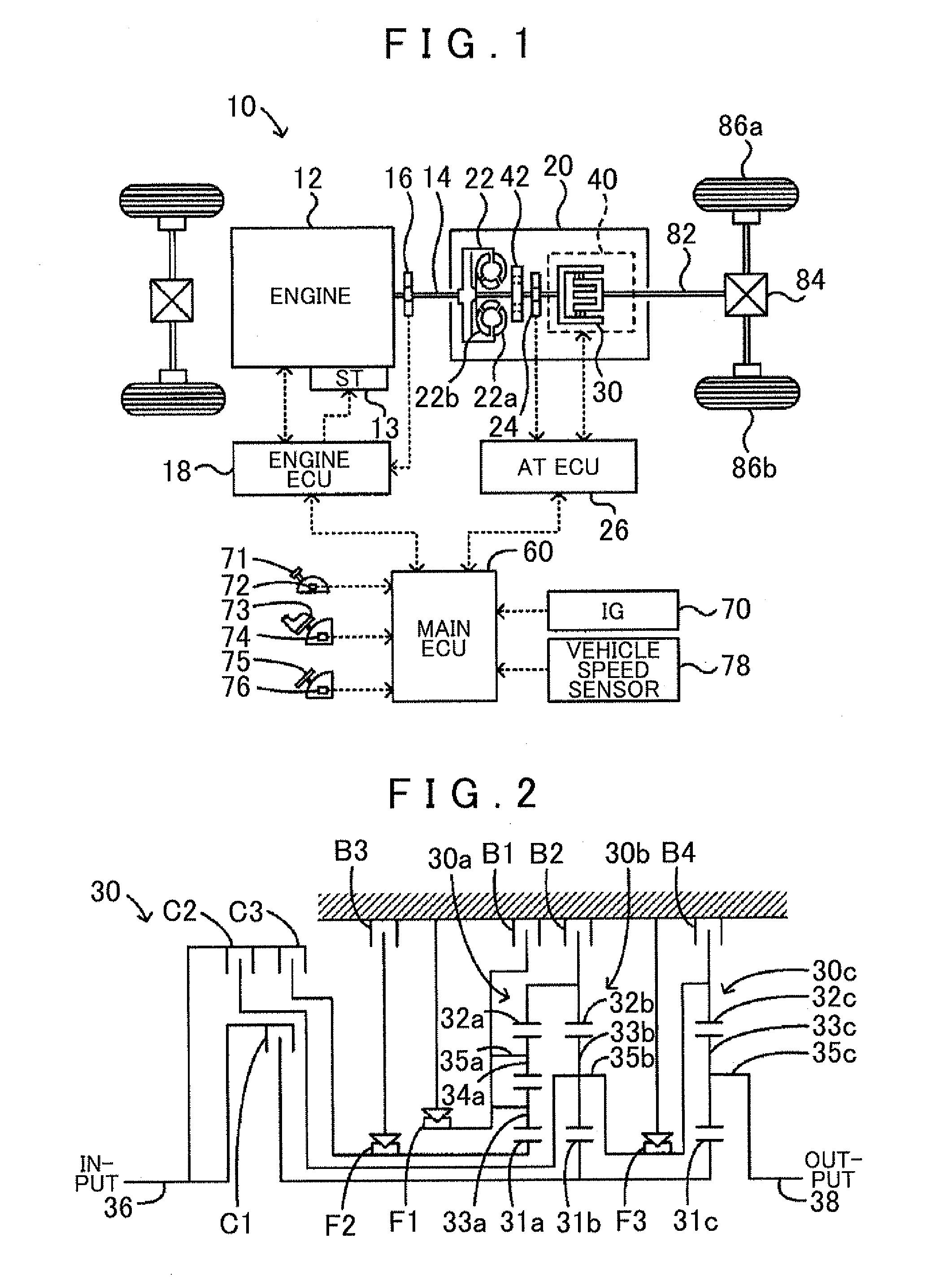
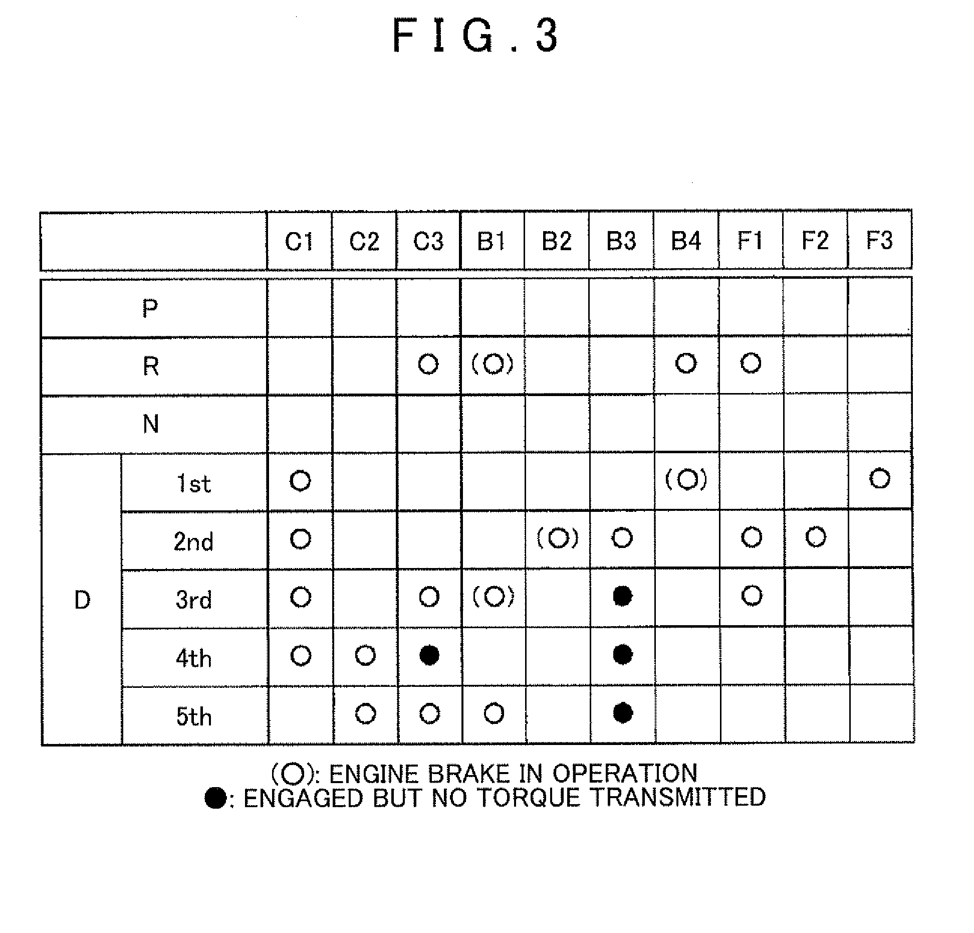
[0029]FIG. 1 is a structural diagram that shows an outline of the constitution of an automobile 10 incorporated with a power transmission device 20 serving as an embodiment of the present invention. FIG. 2 is a structural diagram that shows an outline of the constitution of an automatic transmission 30 provided in the power transmission device 20 of the embodiment. FIG. 3 is an explanatory drawing that shows an operation chart of the automatic transmission 30.

[0030]As FIG. 1 shows, an automobile 10 of the present embodiment includes an engine 12 and a power transmission device 20. The engine 12 is an internal combustion engine that outputs power by explosive combustion of a hydrocarbon fuel such as gasoline or diesel. The power transmission device 20 of the embodiment is connected to a crankshaft 14 of the engine 12, as well as to a drive shaft 82 connected to right and left wheels ...


PUM


Abstract

A power transmission configured with a mechanical pump that generates and deliver a fluid pressure to a clutch. An electromagnetic pump generates and delivers a fluid pressure to the clutch, and an accumulator connects the clutch and the electromagnetic pump, and accumulates fluid pressure acting there between. A switching valve selectively switches between connecting the mechanical pump side and the clutch in a fluid communicating manner and connecting the electromagnetic pump and the clutch in a fluid communicating manner. A valve drive portion that drives the switching valve so as to connect the mechanical pump side and the clutch when the mechanical pump is driving, and drives the switching valve so as to connect the electromagnetic pump and the clutch when the electromagnetic pump is driving in place of the mechanical pump.

Description

INCORPORATION BY REFERENCE[0001]The disclosure of Japanese Patent Application Nos. 2008-298527 filed on Nov. 21, 2008 and 2008-297253 filed on Nov. 20, 2008 including the specifications, drawings and abstracts are incorporated herein by reference in their entirety.BACKGROUND OF THE INVENTION[0002]The present invention relates to a power transmission device and a vehicle having the power transmission device. More specifically, the present invention relates to a power transmission device having an input shaft connected to an output shaft of a motor and an output shaft connected to an axle side of a vehicle, and power input to the input shaft is transmitted to the output shaft by switching an engagement state of a clutch; and a vehicle having the power transmission device.DESCRIPTION OF THE RELATED ART[0003]A conventional vehicle of this type has an engine capable of an automatic stop and an automatic start, and a power transmission device that transmits power from the engine. In such ...

Claims


Application Information

Patent Timeline
IPC IPC(8): F16D25/12
CPCF16H61/0206Y10T477/69377F16H61/067
Inventor SHIMIZU, TETSUYAISHIKAWA, KAZUNORIFUKAYA, NAOYUKIKATO, KAZUHIKOTSUCHIDA, KENICHI
Owner AISIN AW CO LTD
Why Eureka
Try Eureka