
Rocking chair

Inactive Publication Date: 2011-04-21
SCI ROAD INT
View PDF10 Cites 9 Cited by
  • Summary
  • Abstract
  • Description
  • Claims
  • Application Information

AI Technical Summary

Benefits of technology

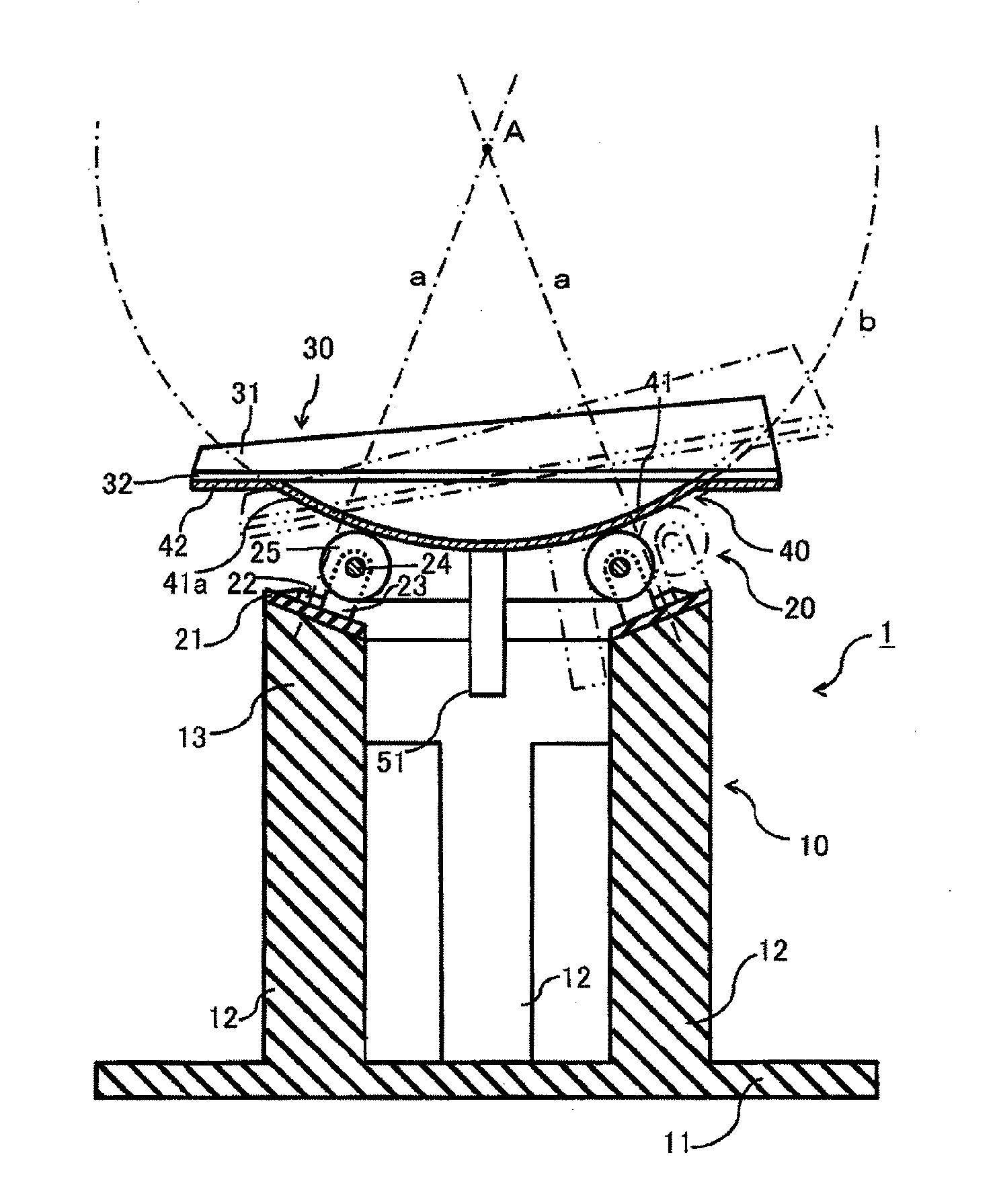
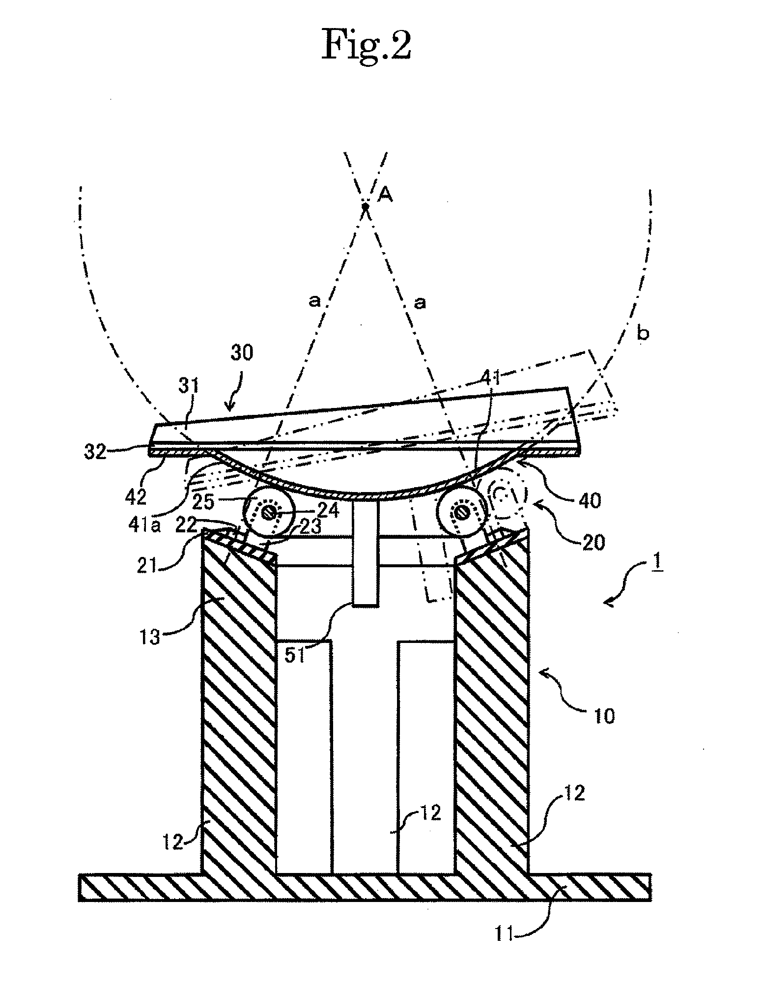
[0020]In the rocking chair of the present invention comprising the projecting member provided on the lower side of the seat and having the convex surface forming a part of the spherical surface centered on the point above the seat, and the guide member for ensuring the rocking motion of the projecting member, the guide member comprises the swivel casters which, in normal use, move two-dimensionally on a flat surface, and each of the swivel casters has the swivel shaft with the central axis passing through the center of the spherical surface. By this specific configuration, the projecting member can be guided in the direction of a force applied through the rollers of the swivel casters, and can rock along the spherical surface. Rocking of the projecting member along the spherical surface is smoother than that in the chair with the ball casters as the guide member. Noise accompanied with the rocking motion of the projecting member is drastically reduced compared to that in the chair having the ball casters, because the swivel casters themselves have good quiet and the movement of the projecting member on the swivel casters is more stable and smoother. Additionally, the rocking chair of the present invention can be produced inexpensively due to the inexpensive swivel casters.

Problems solved by technology

However, the rocking chair as disclosed in JP 2-51540 U having, as the guide member, the base plate with the concave surface corresponding to the convex surface of the projecting member does not have little success in smooth rocking motion of the seat due to friction induced between the concave surface and the convex surface.
The use of the ball casters as the guide member also results in insufficient rocking motion smoothness, the reason is that deformation of the projecting member and the ball casters, which is caused by body weight of the occupant sitting on the seat, increases friction resistance in the rotating motion of the balls and the sliding motion of the projecting member on the balls.
Another problem is very big noise caused by the balls-rotation of the ball casters.
But, only a big and expensive rocking chair is manufactured by this solution.
Highly-refined processing for obtaining exact spherical surfaces also makes the chair expensive

Method used


Image

  • Rocking chair
  • Rocking chair
  • Rocking chair

Examples


Embodiment Construction

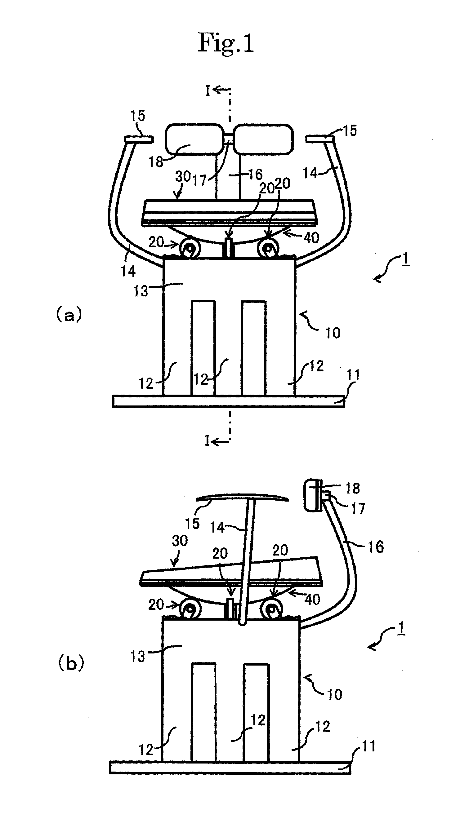
[0023]The present invention will be described in further detail by the following embodiment with reference to the accompanying drawings. FIG. 1(a) and FIG. 1(b) schematically illustrate a front view and a side view of a rocking chair of this embodiment, respectively.

[0024]A rocking chair 1 of this embodiment has, as essential components, a support member 10, swivel casters 20 as a guide member, a seat 30 to be taken by a chair occupant, and a projecting member 40 provided on the lower side of the seat 30.

[0025]The support member 10 has a plate-shaped leg part 11 to be placed on a floor, four pole parts 12 vertically-elongated from the upper side of the leg part 11 and located along a circular line at substantially equidistant spaces, and a cylindrically-shaped mounting part 13 on the end of the pole parts 12. The mounting part 13 has at the side edges a pair of arms for armrest 14. Each of the arms for armrest 14 has a laterally-elongated portion followed by an upwardly-elongated po...


PUM


Abstract

A rocking chair (1) is provided with a seat (30), a projecting member (40) provided on the lower side of the seat (30) and having a convex surface (41a) forming a part of a spherical surface (b) centered on a point (A) located above the seat (30), swivel casters (20) in contact with the convex surface (41a) of the projecting member (40) and guiding the projecting member (40) such that the projecting member (40) can rock along the spherical surface (b), and a support member (10) for the chair. The swivel casters (20) are mounted such that the axes (a) of swivel shafts (22) of the swivel casters (20) pass through the center point (A) of the spherical surface (b), and the seat (30) is guided in the direction of a force applied by rollers (25) of the swivel casters (20). Rocking of the projecting member (40) is smoother than that in rocking chairs using ball casters instead of the swivel casters (20), and noise caused by rocking is drastically reduced. The chair can be produced inexpensively because the swivel casters are inexpensive.

Description

BACKGROUND OF THE INVENTION[0001]1. Field of the Invention[0002]The present invention relates to a rocking chair whose seat taken by a chair occupant can rock on a point above the seat.[0003]2. Description of the Related Art[0004]A rocking chair having a seat taken by a chair occupant performing arc motion around a point above the seat, preferably the point located near a gravity point of the occupant's body, has been developed for the purpose of, for example, recovery of tired lumbar muscle after long-term seating, prevention or treatment of lumbago, and lumbar muscle training in rehabilitation.[0005]Such rocking chair is disclosed in JP 2-51540 U. The chair in this reference literature has a seat, a curved upper plate for supporting the seat which is provided on the lower side of the seat and has a convex surface facing downwardly, and a curved base plate for guiding the upper plate which is located below the upper plate and has a concave surface corresponding to the convex surfac...

Claims


Application Information

Patent Timeline
IPC IPC(8): A47C3/027
CPCA47C3/027A47C3/0257
Inventor NISHINO, ITARU
Owner SCI ROAD INT
Learn More