LED Lighting System

a technology of led lighting and led diodes, which is applied in the direction of general lighting, mass transit vehicle lighting, instruments, etc., can solve the problems of increasing complexity and cost, reducing the efficiency of light fixtures, and adding optics to light fixtures

Inactive Publication Date: 2011-04-21
EMTEQ
View PDF11 Cites 17 Cited by
  • Summary
  • Abstract
  • Description
  • Claims
  • Application Information

AI Technical Summary

Problems solved by technology

Light that is emitted from the fixture at angles greater than the angle of emission for the opening will either be absorbed into or reflected by the surface of the PSU, reducing the efficiency of the light fixture.
However, adding optics to the light fixtures increases complexity and cost.

Method used


Image

  • LED Lighting System
  • LED Lighting System
  • LED Lighting System

Examples


first embodiment

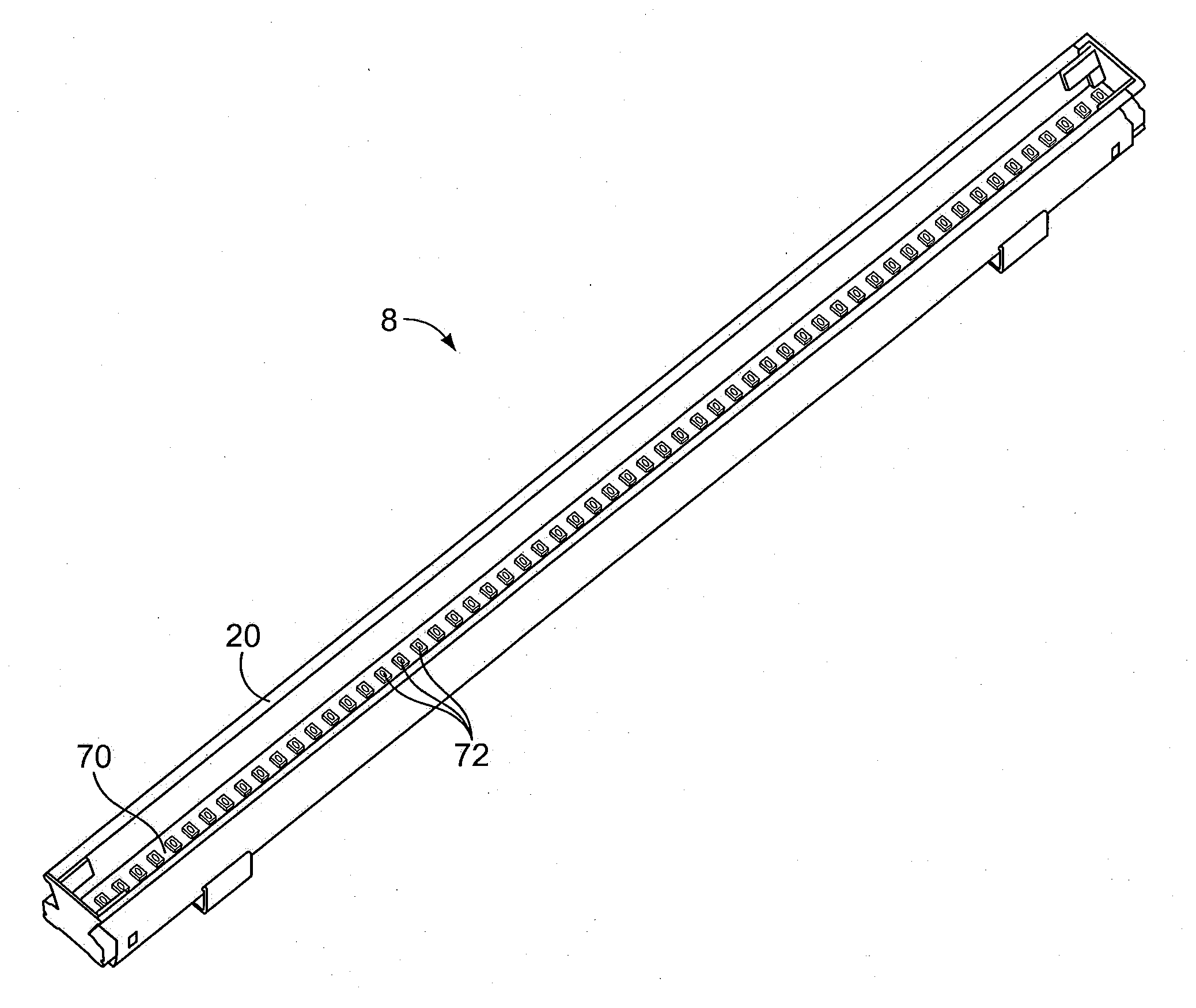
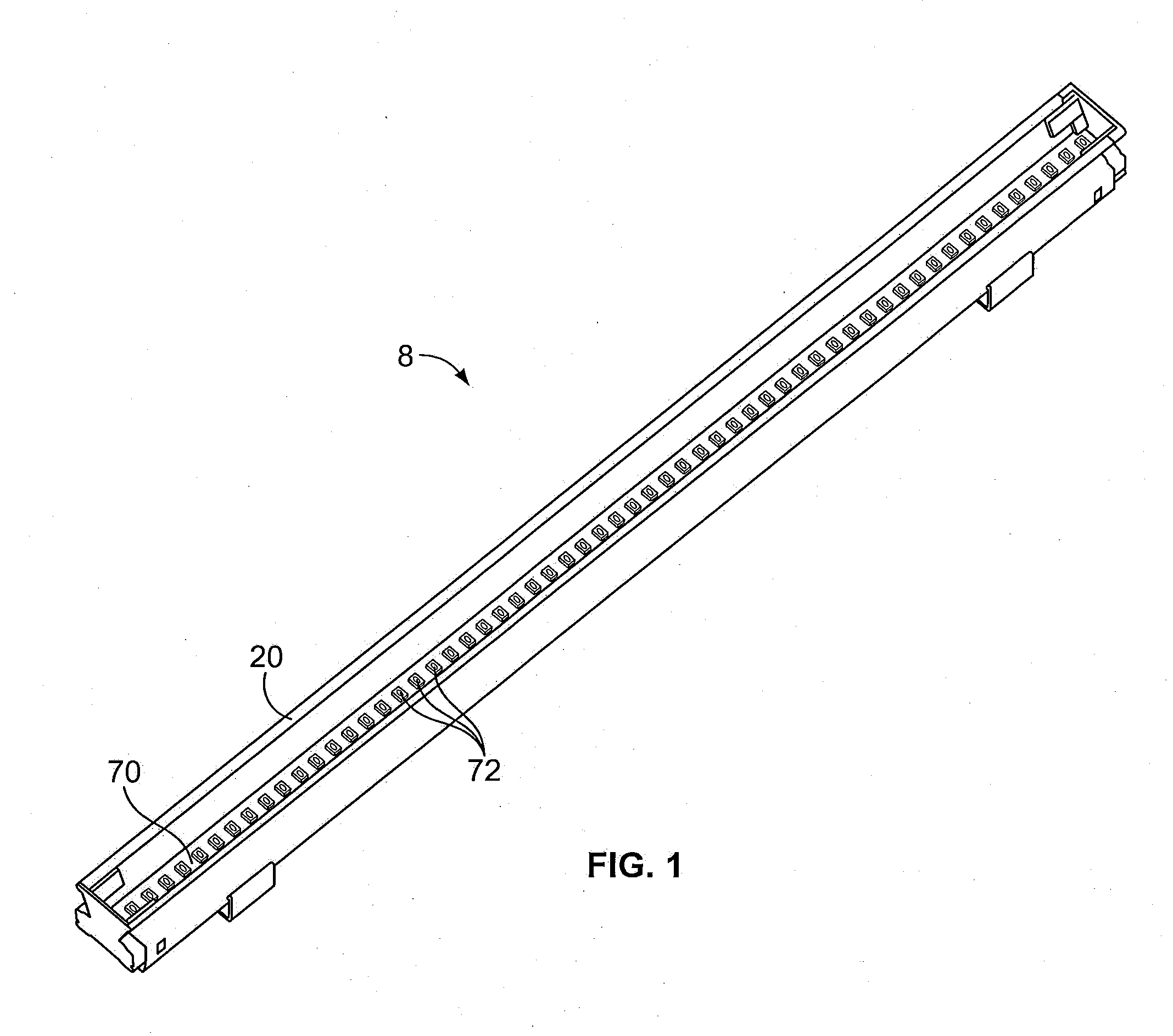
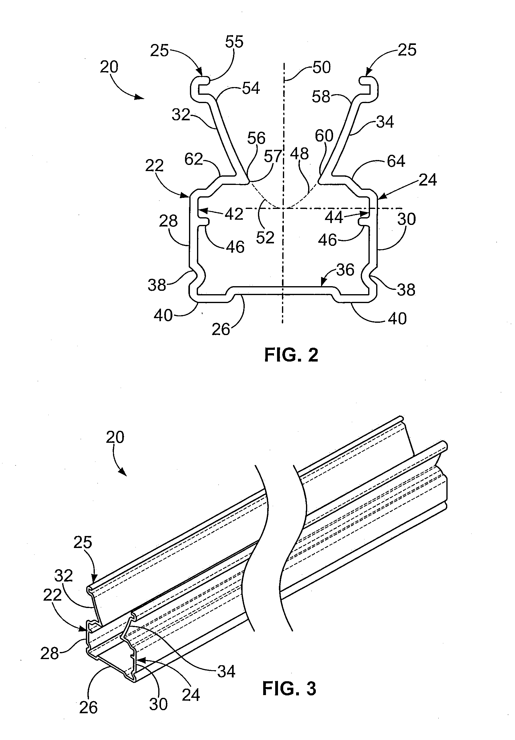
[0050]Referring to FIGS. 1-3, a LED light fixture 8 according to the present invention includes an elongate housing 20 having a first side wall 22; a second side wall 24, generally opposite of the first side wall 22; and a lower surface 26. The housing 20 is generally open along an upper face 25 of the housing 20. The lower surface 26 extends generally perpendicular to the first side wall 22 and the second side wall 24, connecting the side walls, 22 and 24, at a lower edge of each wall. The first side wall 22 includes a first lower section 28 and a first upper section 32, and the second side wall 24 includes a second lower section 30 and a second upper section 34. Each of the lower sections, 28 and 30, is generally straight, and a u-shaped channel 36 is formed between the first lower section 28, the second lower section 30 and the lower surface 26. Optionally, each of the lower sections, 28 and 30, may further include a recessed portion 38 extending into the channel and extending lo...

second embodiment

[0074]In a second embodiment, illustrated in FIG. 12, the upper sections, 32 and 34, have a generally elliptical curvature. The LED 72 emits light at varying angles. On-axis rays 140 may be radiated directly away from the LED 72. Other directly emitted rays 142 are radiated at an off axis angle small enough such that they do not contact the housing 20. In addition, focused rays 146 are radiated at an off axis angle of sufficient magnitude that they are reflected by the housing 20. Because the upper sections, 32 and 34, are generally elliptical, the focused rays 146 are reflected outward through the first opening 55 toward a focal point 148 positioned on-axis and displaced from the LED 72, increasing the intensity of the light exiting the opening 55 in the housing 20.

third embodiment

[0075]In a third embodiment, illustrated in FIG. 13, the upper sections, 32 and 34, may have at least two segments, one segment having a generally elliptical curvature and another segment having a generally parabolic curvature. The LED 72 emits light at varying angles. On-axis rays 140 may be radiated directly away from the LED 72. Other directly emitted rays 142 are radiated at an off axis angle small enough such that they do not contact the housing 20. Directed rays 144 are radiated at an off axis angle that intersects the parabolic segment and reflected outward through the first opening 55 in a direction generally parallel to the first, on-axis, rays 140. Focused rays 146 are radiated at an off axis angle that intersects the elliptical segment and reflected outward through the first opening 55 toward a focal point 148 positioned on-axis and displaced from the LED 72. The combination of directed rays 144 and focused rays 146 from the single housing 20 acts to increase both the amo...


PUM


Abstract

The LED light fixture includes white LEDs having multiple, different color temperatures. Preferably, white LEDs having color temperatures of about 3500 and about 5000 degrees Kelvin (K) are selected. The intensity of each LED may be varied and the light radiated from the LEDs is mixed together. The resulting light emitted from the housing is a white light having a variable color temperature ranging from about 3500 to about 5000 K. The housing is preferably extruded aluminum. A portion of the housing is configured to mix the light together and to focus the light such that the output light is about thirty degrees off center. Electrical loading is off set to minimize load on power supplies.

Description

CROSS-REFERENCE TO RELATED APPLICATIONS[0001]This application claims priority to U.S. provisional application Ser. Nos. 61 / 279,326, filed Oct. 19, 2009, and 61 / 262,821, filed Nov. 19, 2009, both applications entitled “LED Lighting System,” and the entire contents of both applications are incorporated herein by reference.BACKGROUND OF THE INVENTION[0002]1. Field of the Invention[0003]The subject matter disclosed herein relates to light-emitting diode (LED) lighting systems. More specifically, an LED lighting fixture utilizing white LEDs having at least two different color temperatures outputting white light of varying color temperatures.[0004]2. Discussion of the Related Art[0005]Historically, artificial lighting has taken many forms. Artificial lighting has progressed from early flame sources, to modern light fixtures, such as incandescent or fluorescent bulbs. Improvements in artificial lighting have often been driven by desires to provide more natural and / or more efficient lightin...

Claims


Application Information

Patent Timeline
Patent Type & Authority Applications(United States)
IPC IPC(8): H05B37/02
CPCH05B33/0818B64D2011/0038B64D2203/00B60Q3/43B60Q3/47H05B45/24H05B45/37H05B47/175H05B47/16Y02B20/40
Inventor TROTTER, MATTHEW A.HOBSON, CHARLES O.FREDRICH, JEREMY J.WASNIEWSKI, CORY
Owner EMTEQ
Why Eureka
Try Eureka