Confocal optical scanner

a scanner and optical technology, applied in the field ofconfocal optical scanners, can solve the problems of not meeting a request, the magnification of the objective lens cannot be optimized for the optical system, and the pinhole size cannot be changed

Inactive Publication Date: 2011-04-21
YOKOGAWA ELECTRIC CORP
View PDF5 Cites 12 Cited by
  • Summary
  • Abstract
  • Description
  • Claims
  • Application Information

AI Technical Summary

Benefits of technology

[0015]According to the confocal optical scanner, the pinhole disc is caused to undergo reciprocating transfer between a position where the pinhole disc resides in an optical path of the illumination light, and a position where the pinhole disc is evacuated from the optical path, to thereby cause the confocal optical scanner to cope with variation of optical system magnification, a bright field image, and so forth.

Problems solved by technology

However, according to a conventional apparatus, the size of pinholes can't be changed and an objective lens magnification can't be optimized for an optical system.
Further, there is a problem in the conventional apparatus that it does not comply with a request of observation of a bright field image such as a phase-contrast image as well as a confocal image of a sample.

Method used


Image

  • Confocal optical scanner
  • Confocal optical scanner
  • Confocal optical scanner

Examples


second embodiment

[0042]A confocal optical scanner according to a second embodiment is now described with reference to FIG. 5 to FIG. 6.

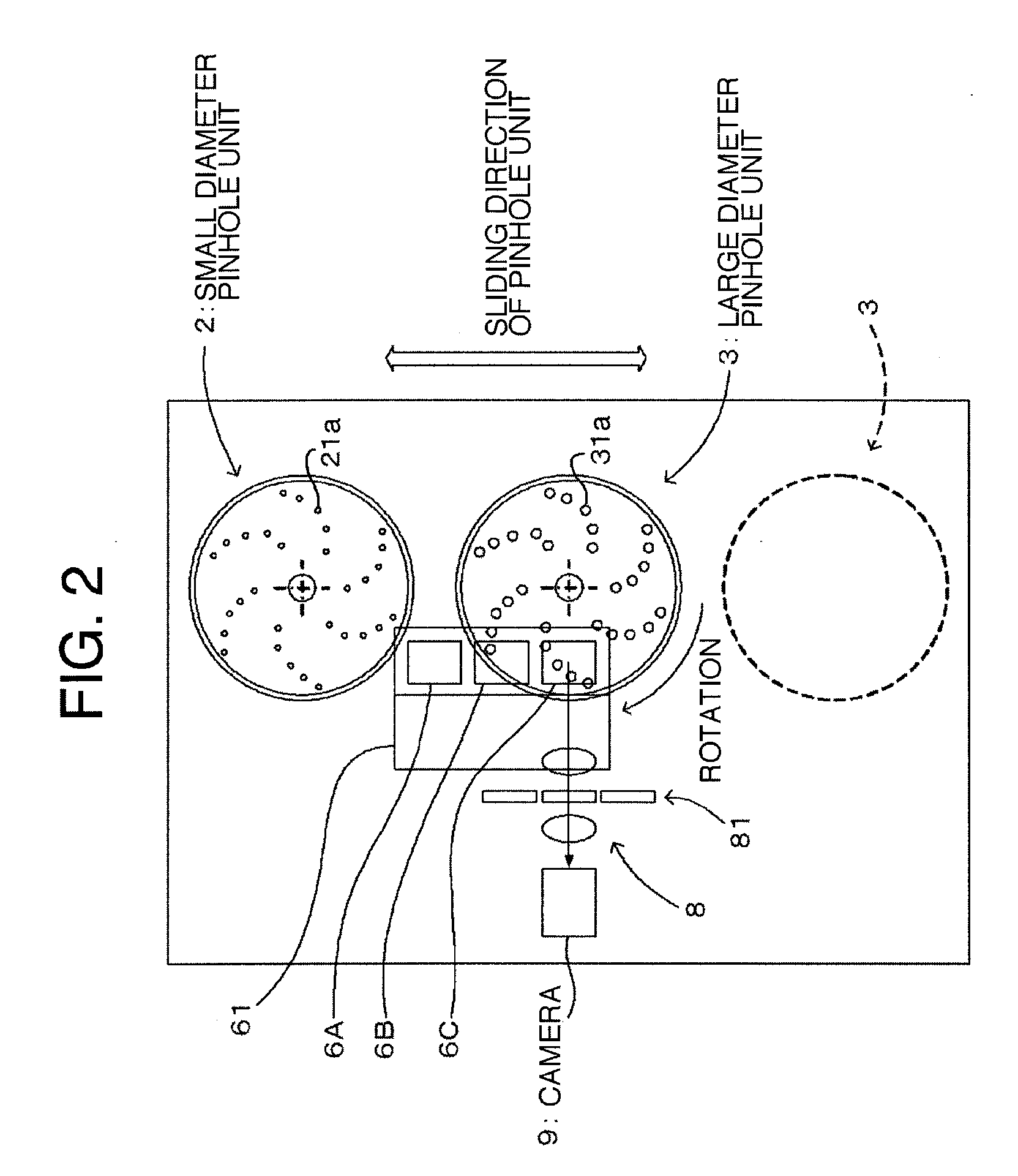
[0043]FIG. 5 and FIG. 6 are plan views respectively showing a confocal microscope constituting a confocal optical scanner according to the second embodiment of the invention. In FIG. 5 and FIG. 6, elements same as those of the confocal optical scanner according to the first embodiment are denoted by the same reference numerals.

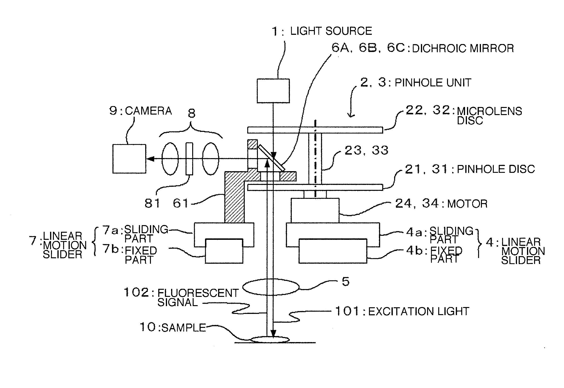
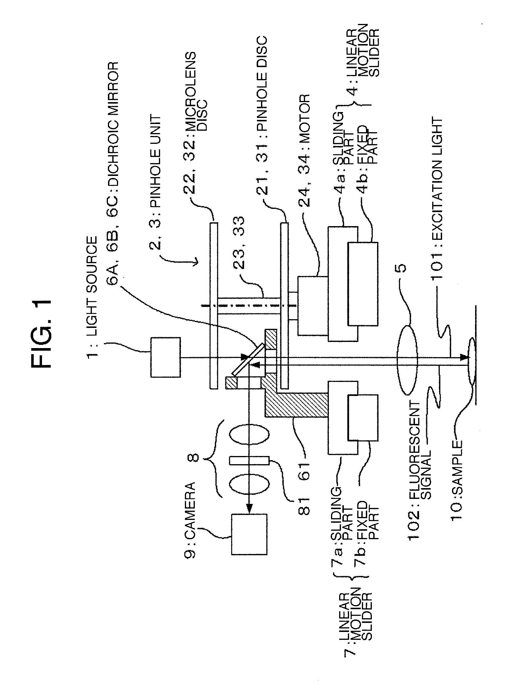
[0044]As shown in FIG. 5, according to the confocal optical scanner of the second embodiment, a single dichroic mirror 6 is disposed between a microlens disc and a pinhole disc. A small diameter pinhole unit 2 or a large diameter pinhole unit 3 can be selectively located at an optical path in response to magnification of an objective lens by sliding the small diameter pinhole unit 2 or the large diameter pinhole unit 3. FIG. 5 shows a state where the large diameter pinhole unit 3 is located on the optical path while FIG. 6 shows the state where...


PUM


Abstract

There is provided a confocal optical scanner capable of coping with variation of optical system magnification, a bright field image, and so forth. The confocal optical scanner comprising a pinhole disc with pinholes provided thereon, and rotation means for rotating the pinhole disc for obtaining a confocal image by rotating the pinhole disc with the use of the rotation means to thereby scan with illumination light and by causing optical feedback from the illumination light passing through the pinholes to form an image, wherein the confocal optical scanner is provided with a transfer mechanism for causing the pinhole disc to undergo reciprocating transfer between a position where the pinhole disc resides in an optical path of the illumination light, and a position where the pinhole disc is evacuated from the optical path of the illumination light.

Description

FIELD OF THE INVENTION[0001]The present invention relates to a confocal optical scanner for obtaining a confocal image by rotating a pinhole disc to thereby scan with illumination light and by causing optical feedback from the illumination light passing through the pinholes to form an image.BACKGROUND OF THE INVENTION[0002]There has been known a nipkow confocal scanner provided with multiple microlenses, two discs each having minute apertures of the same pattern and arranged in an array, rotation means for rotating two discs synchronously, a beam splitter inserted between two discs, an objective lens interposed between two discs and a sample. It is possible to obtain a confocal image of the sample by rotating two discs to thereby concurrently execute scanning with illumination light and selection of reflected light.[0003]The following documents are exemplified as prior arts.[0004]Patent Document: JP 2008-233543A[0005]Patent Document: JP 2009-210889A[0006]However, according to a conv...

Claims


Application Information

Patent Timeline
Patent Type & Authority Applications(United States)
IPC IPC(8): G02B26/10
CPCG02B21/0032G02B21/0076G02B21/0044
Inventor KEI, TAKAYUKI
Owner YOKOGAWA ELECTRIC CORP
Why Eureka
Try Eureka