Lidar optical scanner system

a scanning system and optical scanner technology, applied in the field of timeofflight distance measurement, can solve the problems of inefficient use of scanning time, power consumption, mechanical scanning field, etc., and achieve the effect of reducing system complexity

Active Publication Date: 2015-09-17
GARMIN
View PDF4 Cites 64 Cited by
  • Summary
  • Abstract
  • Description
  • Claims
  • Application Information

AI Technical Summary

Benefits of technology

[0018]For rotational scanner applications, the line scan pattern's fields-of-coverage are tangential to the rotation axis of the system. For applications requiring full 360 degrees azimuth coverage, such as for robotic navigation, continuous rotation of the housing may be desirable. For continuous rotation, placement of the multiple lenses sharing a center oriented detector array offers reduced sy...

Problems solved by technology

The primary limitation of mechanically scanning the field of view using a steering mirror is a complex trade-off between power consumption, weight and size of the scanner, efficient use of the optical beam power and stray light rejection.
If the mirror scans a raster pattern over a rectangular field-of-view, the requirement to rapidly accelerate and decelerate the mirror increases power consumption and results in the inefficient use of the scanning time.
An external, multiple-facet, rotating polygon mirror scanner can produce a rapid scanning pattern, but is limited to small transmit and receive apertures.
This configuration allows the scanning of a larger receiver and transmit beam at the expense of a potentially undesirable by-product, the rotation of the relative position of the transmitted beam and the receiver field.
When the exiting beam and receive field needs to pass through the curved optic of a cylindrical window or dome the relationship between the transmitted and received fields rotates, resulting in changing optical distortion and the potential for large amount of...

Method used


Image

  • Lidar optical scanner system
  • Lidar optical scanner system
  • Lidar optical scanner system

Examples


Embodiment Construction

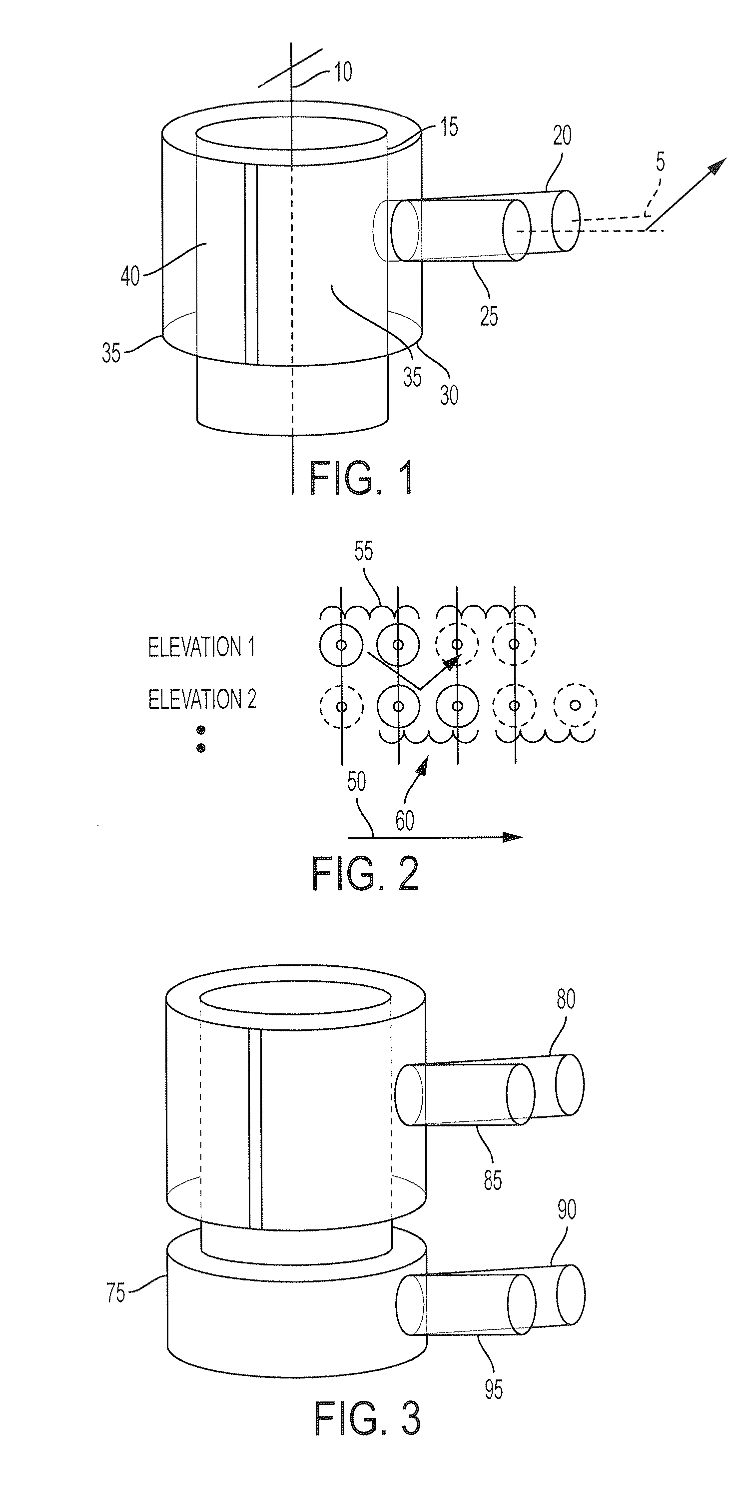
[0048]FIG. 1 illustrates a generic embodiment of a cylindrical shaped optical scanner receiver with external beam deflector. Inter housing 15, is shown with a central-axis 10. Two optical receive fields labeled 20 and 25 are displaced in azimuth in order to provide a look-ahead function to fill in coverage gaps resulting when external scanner component 30, selects alternating regions of elevation. Elevation deflection produced from regions 35 and 40 may be constructed using diffractive or refractive optics or in an alternate embodiment by an opaque mask used selectively block a range of elevation coverage. Although two separate elevation selection levels are shown, any number of elevation regions may be implemented based on the circumference of the scanner and the number of elevation scans per rotation.

[0049]FIG. 2 illustrates receiver field-of view coverage projected onto a plane due continuous lateral motion of the receiver optical axis. Two scanner elevations are illustrated alon...


PUM


Abstract

An optical scanner system comprises a housing, a detector contained within the housing configured to produce at least two resolvable azimuth fields-of-view relative to a center-axis of the housing, and an external scanner rotating relative to the center-axis of the housing, and switching between at least two elevations relative to a nominal optical axis of a receiver. Motion of the housing azimuthally results in the receiver producing a continuous coverage pattern at multiple elevations produced by the external scanner.

Description

CROSS REFERENCE TO RELATED APPLICATION[0001]This application claims the benefit of U.S. Provisional Application No. 61 / 952,803, filed Mar. 13, 2014, which is incorporated herein by reference in its entirety.TECHNICAL FIELD[0002]The disclosure pertains to time-of-flight distance measurement within a volume.BACKGROUND OF THE INVENTION[0003]Various methods are available to mechanically scan an optical beam and an associated receiver field-of-view through a region with the distance measurement based on the calculated round trip delay between the emission of a light pulse in the direction of an object and the subsequent reception of the received signal. The common approach for implementation of the scanning function is the use a mechanical steering mirror driven by an actuator to steer the beam and receiver field of view through the desired region. An alternative approach is to mount the transmitter and receiver on a moving platform such as a multiple-axis gimbals or rotary platform to a...

Claims


Application Information

Patent Timeline
IPC IPC(8): G01S17/02G02B19/00G01S7/481G02B26/10
CPCG01S17/02G02B26/108G01S7/4813G02B19/0028G02B19/0085G02B26/106G01S7/4817G01S17/42
Inventor LEWIS, ROBERT A.
Owner GARMIN
Why Eureka
Try Eureka