String and system employing direct current electrical generating modules and a number of string protectors

Inactive Publication Date: 2011-04-21
EATON CORP
View PDF8 Cites 64 Cited by
  • Summary
  • Abstract
  • Description
  • Claims
  • Application Information

AI Technical Summary

Benefits of technology

[0010]These needs and others are met by embodiments of the disclosed concept, which detect arcing in a series-connected string of direct current electrical generating modules and interrupt the flow of current in the event that, for example and without limitation, an “in-circuit” arc (commonly referred to as a series arc) or a “short circuit” arc (commonly referred to as a parallel arc) occurs. This also pr

Problems solved by technology

It is believed that there is no known mechanism in photovoltaic (PV) (e.g., photovoltaic; solar electric) systems to stop strings or string arrays from generating energy under a short circuit fault (e.g., without limitation, a parallel arc), which can result in a fire.
For example, fuses at the load end of a string do not prevent

Method used


Image

  • String and system employing direct current electrical generating modules and a number of string protectors
  • String and system employing direct current electrical generating modules and a number of string protectors
  • String and system employing direct current electrical generating modules and a number of string protectors

Examples


example 1

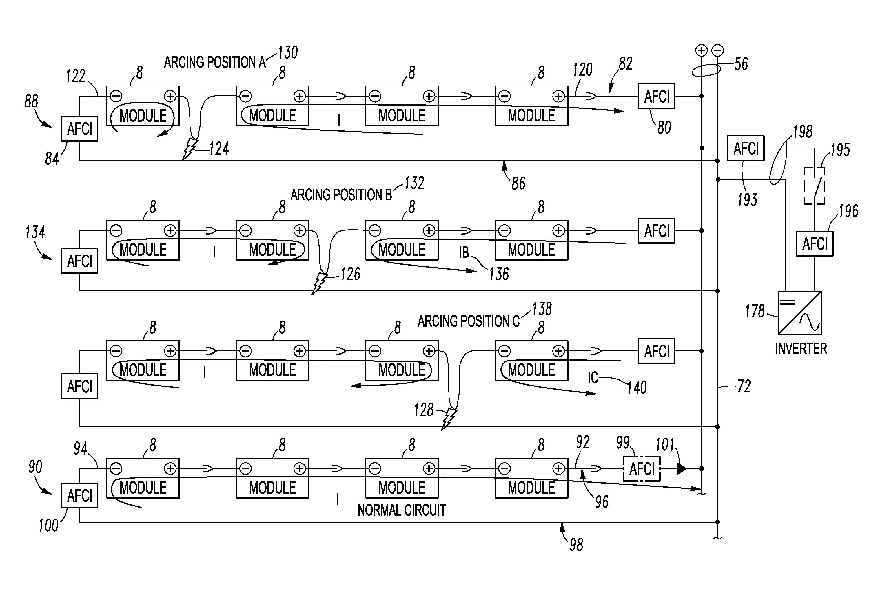
[0072]An example string 90 includes a plurality of direct current (DC) electrical generating modules (EGMs) 8 (shown as modules in FIG. 3) electrically connected in series to form a first end 92 and a remote second end 94, a power line 96 electrically connected to one of the DC EGMs 8 at the first end 92, a return line 98 electrically connected to another one of the DC EGMs 8 at the remote second end 94, and a SP 100 (e.g., without limitation, AFCI) in the return line 98 of the string 90. As will be described, below, in connection with FIG. 7, the SP 100 includes a number of an over current protector, an arc fault protector, a reverse current protector and a ground fault protector.

[0073]In this example, an SP 99 (e.g., without limitation, AFCI) (shown in phantom line drawing) in the power line 96 of the string 90 is not required for in-circuit (series) only faults. Preferably, a diode 101 is disposed in the power line 96 at the first end 92 of the string 90. This eliminates the need...

example 2

[0074]The example SP 100 is structured to monitor or report current flowing in the power line 96 of the string 90. For example, as shown in FIG. 7, the example SP 100 includes a current sensor 102, an analog front end 104 and a processor 106 (e.g., without limitation, microprocessor) that monitors the sensed string current 108 and reports the same (e.g., without limitation, through communication port 110). The processor 106 includes a number (e.g., one, some or all) of an over current protector routine 112, an arc fault protector routine 114, a reverse current protector routine 116 and a ground fault protector routine 118.

[0075]A non-limiting example of DC arc fault detection and protection for the routine 114 is disclosed by U.S. Pat. No. 6,577,138, which is incorporated by reference herein.

[0076]If DC ground fault protection is employed, then, for example and without limitation, a current sensor 102′ and an analog front end 104′ provide a string return current 108′ to the processo...

example 3

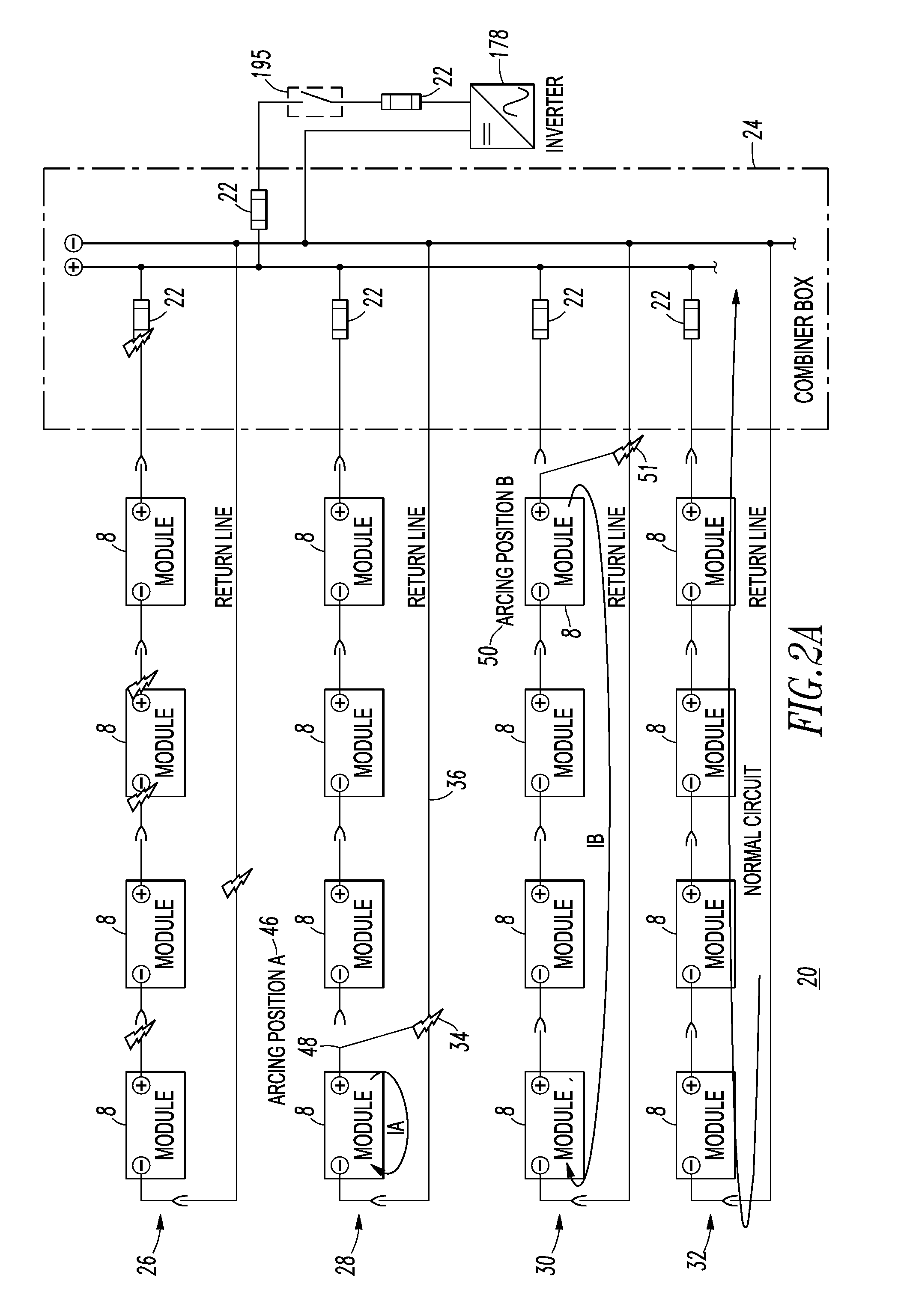
[0077]The example SP 100 (FIG. 3) is located at the remote second end 94 of the string 90 with one of the DC EGMs 8. This SP 100 can advantageously be employed for retrofit applications, such that an electrician does not have to go into a combiner box (e.g., 24 of FIGS. 2A-2C) to install a protective device or rewire. Instead, the electrician simply installs (e.g., without limitation, plugs-in) the SP 100 at the last DC EGM 8 (with respect to FIG. 3, at the left of the string 90).


PUM


Abstract

A string includes direct current electrical generating modules electrically connected in series to form a first end and a remote second end. A power line is electrically connected to one DC EGM at the first end. A return line is electrically connected to another DC EGM at the remote second end. A first string protector is in the power line of the string, and a second SP is in the return line of the string at the remote second end. One of the first and second SPs includes a number of an over current protector, an arc fault protector, a reverse current protector and a ground fault protector. The other one of the first and second SPs includes a number of an over current protector, an arc fault protector, a reverse current protector, a ground fault protector, and a remotely controlled switch in series with the power or return lines.

Description

BACKGROUND[0001]1. Field[0002]The disclosed concept pertains generally to strings and, more particularly, to such strings including a plurality of direct current electrical generating modules, such as, for example, photovoltaic electrical generating modules. The disclosed concept also pertains to systems, single strings, multiple strings that make an array, and multiple arrays such as string arrays, including a number of strings having a plurality of direct current electrical generating modules.[0003]2. Background Information[0004]It is believed that there is no known mechanism in photovoltaic (PV) (e.g., photovoltaic; solar electric) systems to stop strings or string arrays from generating energy under a short circuit fault (e.g., without limitation, a parallel arc), which can result in a fire. For example, fuses at the load end of a string do not prevent this fault. For example, arcs consume energy that does not go to an inverter or load.[0005]Known practice places a protective de...

Claims


Application Information

Patent Timeline
IPC IPC(8): H02H3/00
CPCH01L31/02021H02H7/20H02H7/262H02H1/0015Y02E10/56H02H3/00
Inventor LUEBKE, CHARLES J.HASTINGS, JEROME K.PAHL, BIRGERZUERCHER, JOSEPH C.YANNIELLO, ROBERT
Owner EATON CORP
Why Eureka
Try Eureka