Temperature sensor mounting arrangement for a battery frame assembly

a technology for temperature sensors and battery frame assemblies, which is applied in the direction of cell components, basic electric elements, substation/switching arrangement details, etc., can solve the problems of inaccurate battery temperature control and often less than optimal solutions, and achieve the effect of improving thermal conductivity and high-speed assembly

Inactive Publication Date: 2011-04-21
MANN HUMMEL GMBH
View PDF2 Cites 14 Cited by
  • Summary
  • Abstract
  • Description
  • Claims
  • Application Information

AI Technical Summary

Benefits of technology

[0013]In another aspect of the invention, an electrically insulating sheet is provided between the support member and the outer surface of the nearby battery pack. Preferably the insulating sheet is secured to the frame member by the same mounting members used to secure the support member to the frame member, thereby further aiding high speed assembly of the battery frames.
[0014]In another aspect of the invention, the insulating sheet includes an opening therethrough positioned in a location between the temperature sensor device and the outer surface of the battery pack. The opening enables improved temperature response (shortened response time) of said temperature sensor without the insulating / dampening effects of the insulator sheet.
[0018]In another aspect of the invention, a silicone based potting material is arranged on the elongated support member to encapsulate the temperature sensor, thereby protecting the temperature sensor and providing further electrical insulation. Preferably the potting material is adapted for improved thermal conductivity.
[0019]In another aspect of the invention, the support member is fixedly secured to the frame member by at least one thermally activated mounting member, allowing for high speed assembly.

Problems solved by technology

Such solutions are often less than optimal as they may often interfere with replacement of a defective battery pack in a battery frame assembly.
It is also possible that the temperature sensor device does not remain optimally and correctly positioned relative to the battery pack during its service life, thereby resulting in inaccurate battery temperature detection and resulting in inaccurate battery temperature control.

Method used


Image

  • Temperature sensor mounting arrangement for a battery frame assembly
  • Temperature sensor mounting arrangement for a battery frame assembly
  • Temperature sensor mounting arrangement for a battery frame assembly

Examples


Embodiment Construction

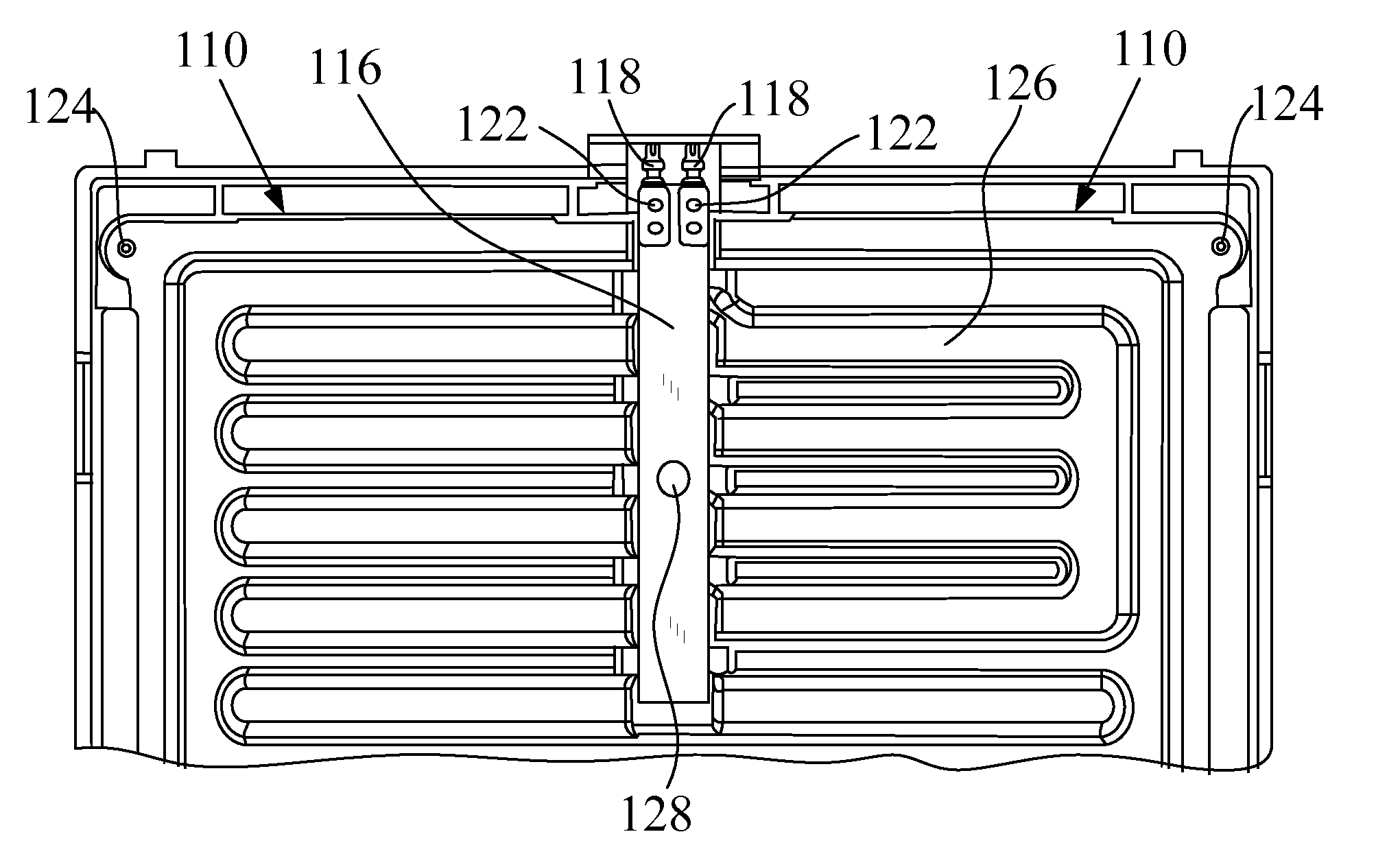
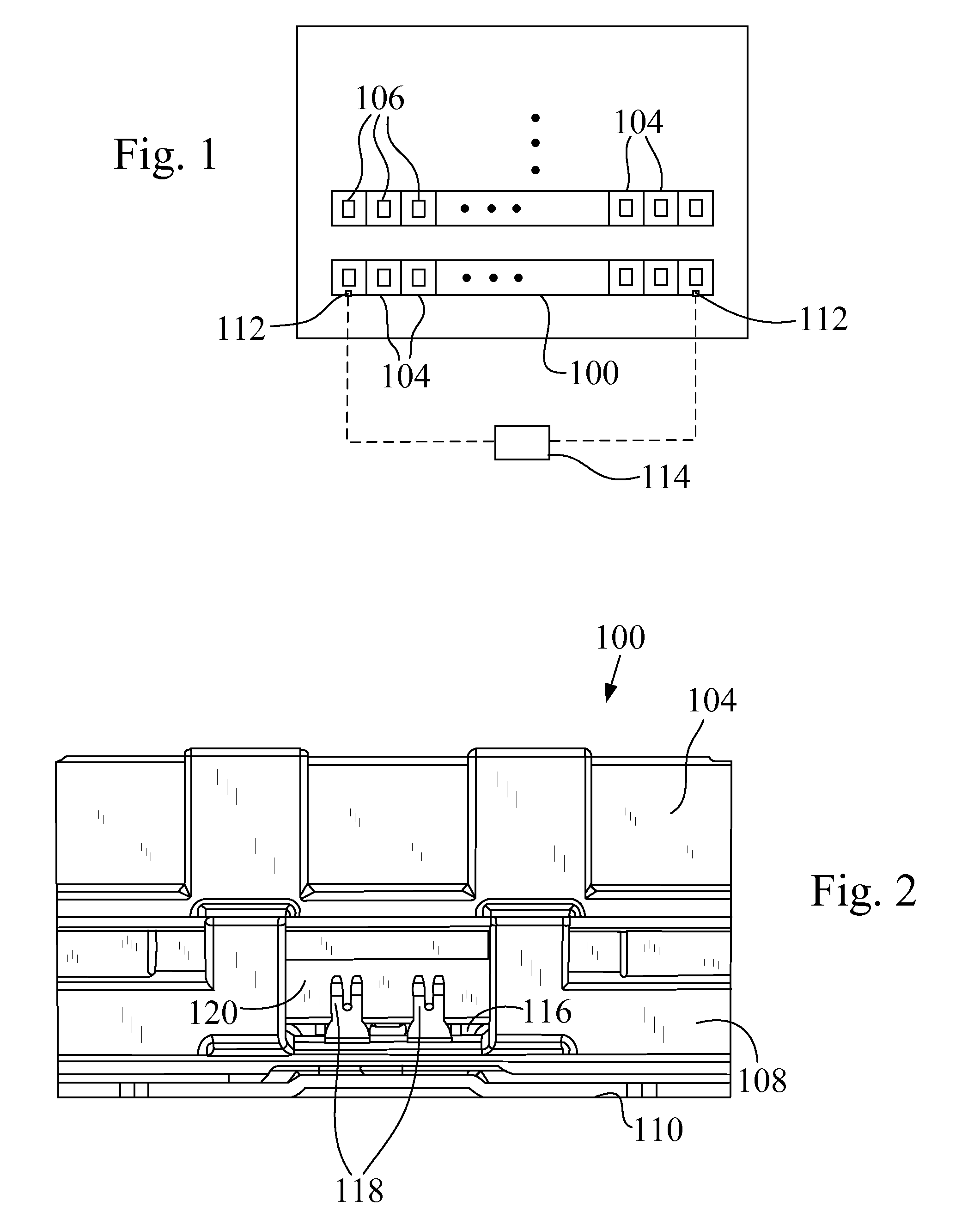
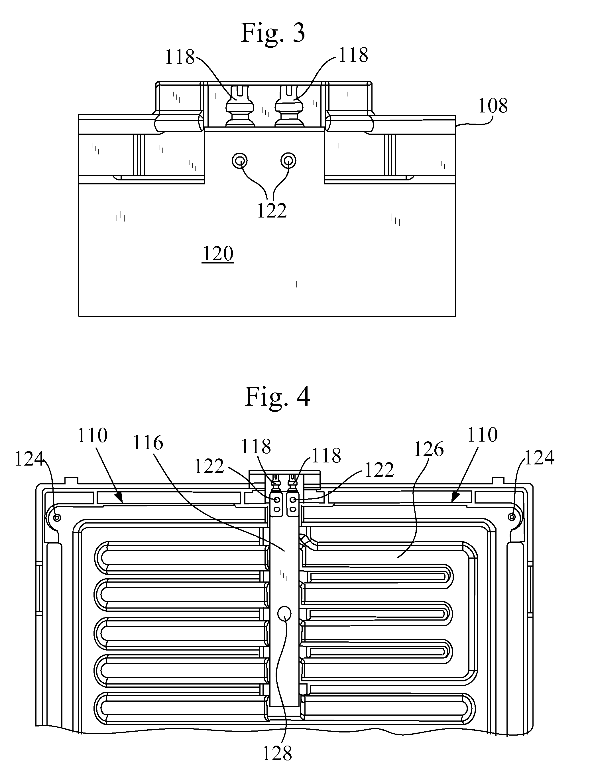
[0031]Before describing in detail embodiments that are in accordance with the present invention, it should be observed that the embodiments reside primarily in combinations of method steps and apparatus components related to a modular temperature sensor mounting arrangement for a battery frame assembly packaging one or more interconnected battery packs. Accordingly, the apparatus components have been represented where appropriate by conventional symbols in the drawings, showing only those specific details that are pertinent to understanding the embodiments of the present invention so as not to obscure the disclosure with details that will be readily apparent to those of ordinary skill in the art having the benefit of the description herein.

[0032]In this document, relational terms such as first and second, top and bottom, and the like may be used solely to distinguish one entity or action from another entity or action without necessarily requiring or implying any actual such relation...


PUM

PropertyMeasurementUnit
temperatureaaaaaaaaaa
speedaaaaaaaaaa
rigidityaaaaaaaaaa

Abstract

A temperature sensor mounting arrangement for a battery frame assembly in which a plurality of rechargeable battery packs are supported and interconnected. The arrangement includes an elongated support member secured to a battery frame member and extending into an interior region of the frame member. At least one electrical interface connector is secured to a first end of the support member and an electronic temperature sensor is secured to a face of the support member in a target position proximate to a battery pack outer surface. A plurality of electrical conductors interconnects between the electrical connectors and the temperature sensor. The temperature sensor mounting arrangement is modularized and designed to enable high speed assembly during manufacturing and ensure repeatable frame to frame sensor positioning and accuracy of temperature readings.

Description

CROSS REFERENCE TO RELATED APPLICATIONS[0001]The present application claims the benefit of U.S. Provisional Patent Application No. 61 / 253,149, filed Oct. 20, 2009 entitled “TEMPERATURE SENSOR MOUNTING ARRANGEMENT FOR A BATTERY FRAME ASSEMBLY” and which is hereby incorporated by reference in its entirety.TECHNICAL FIELD[0002]The present invention relates to rechargeable battery frame assemblies for electrically powered vehicles and, more particularly, to a modular temperature sensor mounting arrangement for such battery frame assemblies.BACKGROUND OF THE INVENTION[0003]Electric and hybrid electric vehicles are seen as offering advantages in the reduced use of petroleum and fossil fuels as well as in reduced emissions of green house gases.[0004]“Plug-in” electric vehicles and more conventional hybrid internal combustion and electrically operated vehicles require substantial numbers of rechargeable storage battery packs for chemically storing and providing the required electrical energ...

Claims


Application Information

Patent Timeline
Patent Type & Authority Applications(United States)
IPC IPC(8): H02B1/01H01M50/204H01M50/264H01M50/296
CPCH01M2/1077H01M10/486H01M10/5061H01M10/5016H01M10/5004H01M10/625H01M10/613H01M10/656Y02E60/10H01M50/204H01M50/264H01M50/296
Inventor RUPERT, CHARLESENDRES, JOHNRINDERSPACHER, FRANKWILSON, RICHARD
Owner MANN HUMMEL GMBH
Why Eureka
Try Eureka