Housing for a LED Lighting System
a technology of led lighting and housing, which is applied in the direction of general lighting, lighting support devices, mass transit vehicle lighting, etc., can solve the problems of increasing complexity and cost, reducing the efficiency of light fixtures, and adding optics to light fixtures
- Summary
- Abstract
- Description
- Claims
- Application Information
AI Technical Summary
Problems solved by technology
Method used
Image
Examples
first embodiment
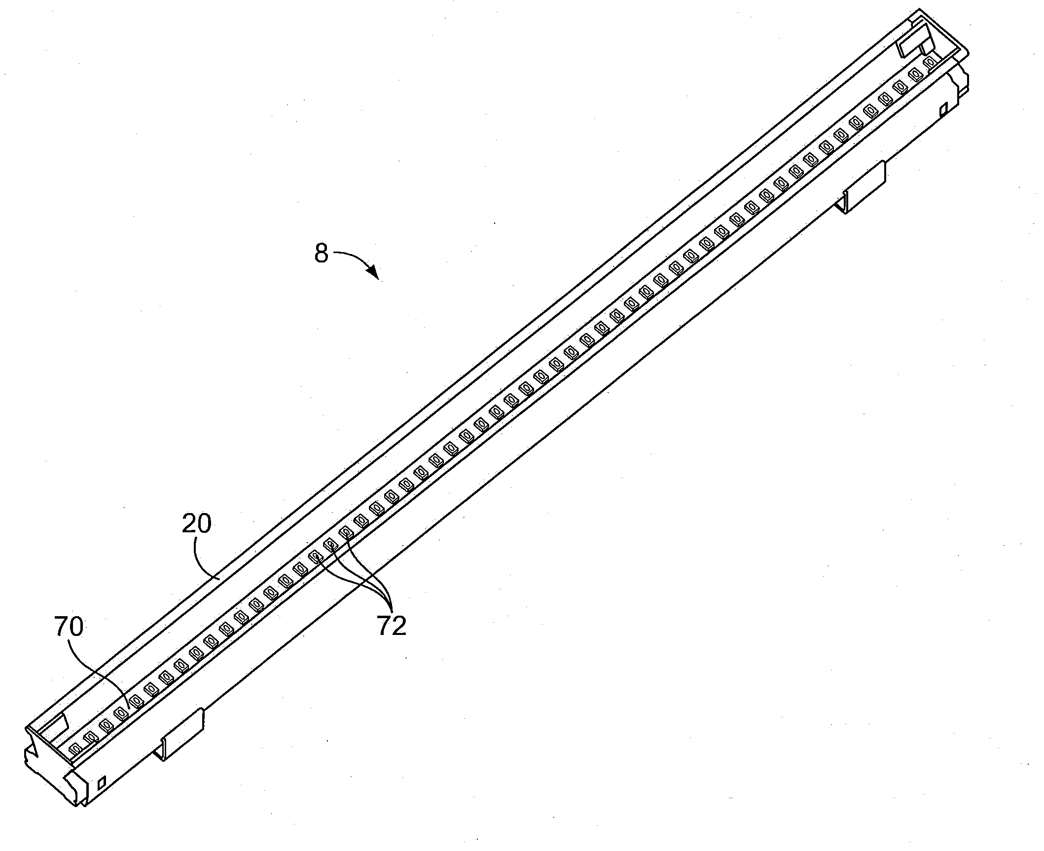
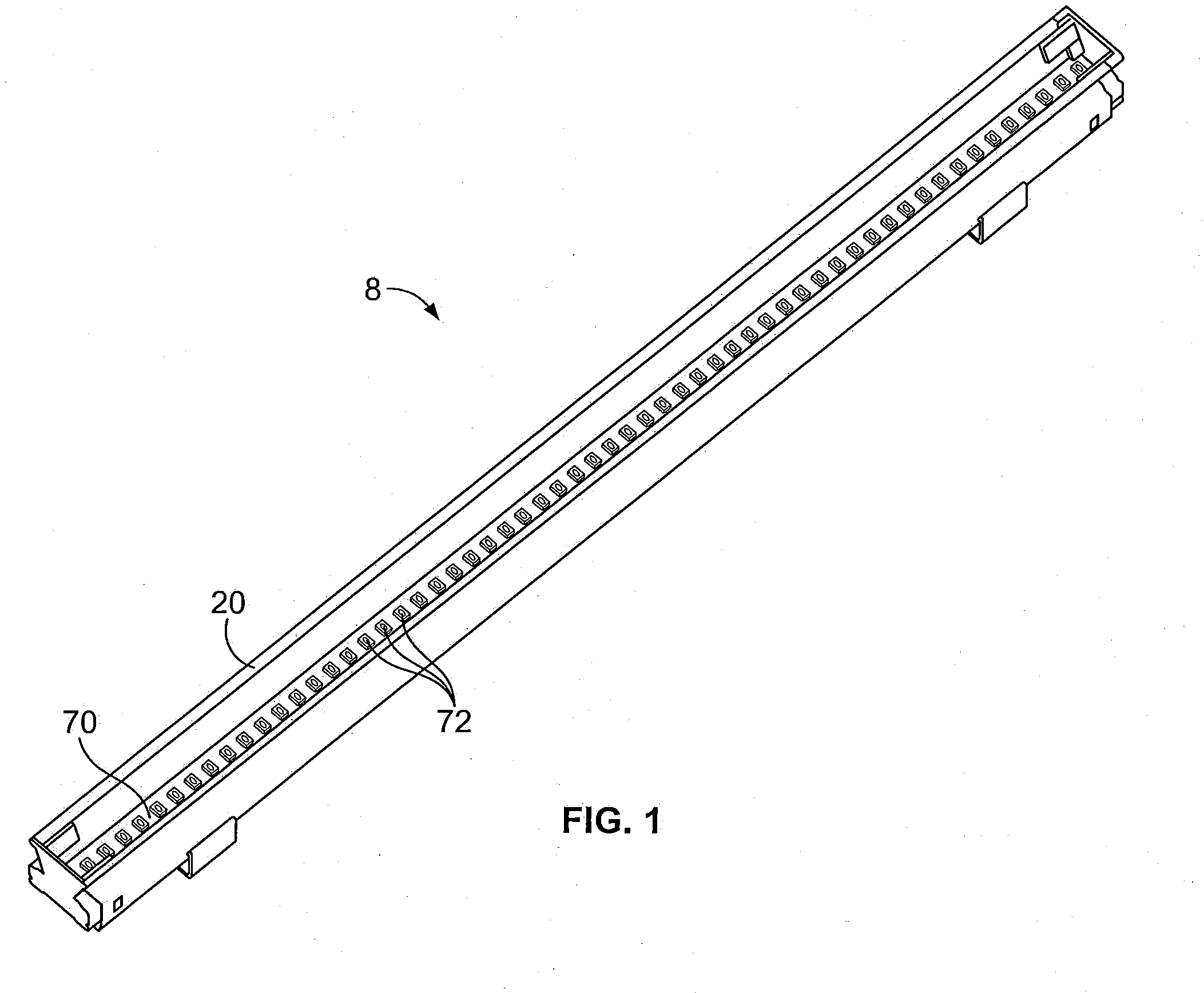
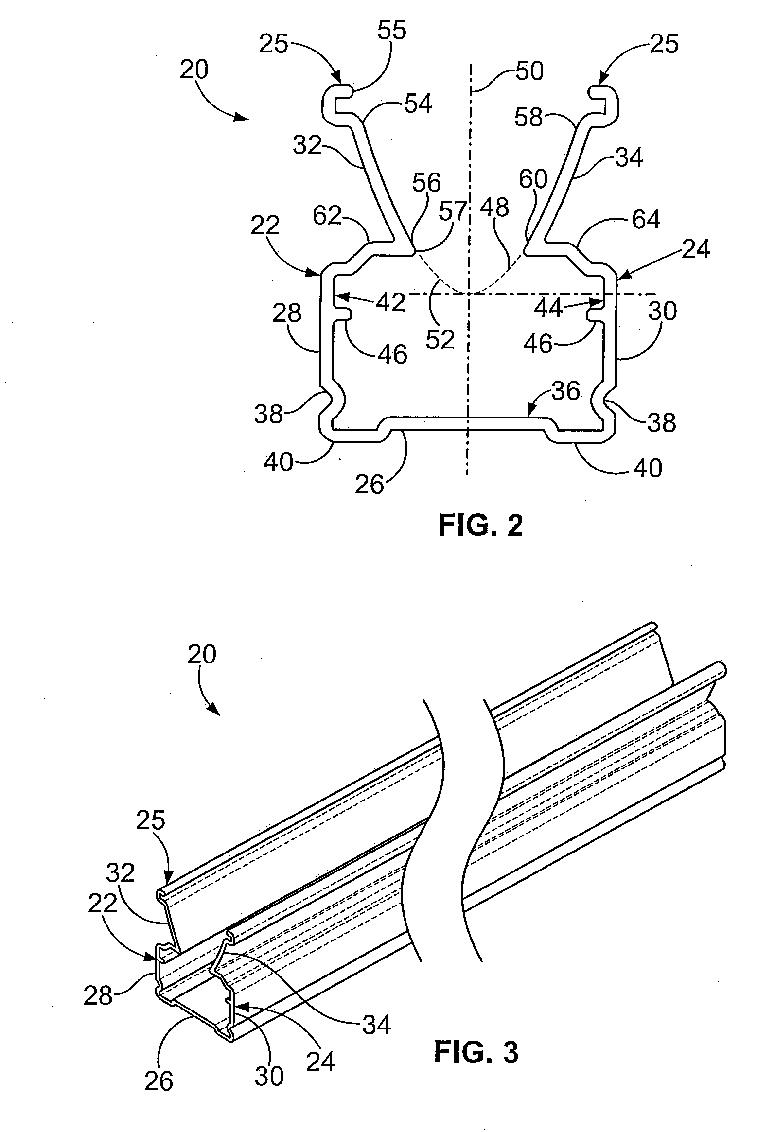
[0050]Referring to FIGS. 1-3, a LED light fixture 8 according to the present invention includes an elongate housing 20 having a first side wall 22; a second side wall 24, generally opposite of the first side wall 22; and a lower surface 26. The housing 20 is generally open along an upper face 25 of the housing 20. The lower surface 26 extends generally perpendicular to the first side wall 22 and the second side wall 24, connecting the side walls, 22 and 24, at a lower edge of each wall. The first side wall 22 includes a first lower section 28 and a first upper section 32, and the second side wall 24 includes a second lower section 30 and a second upper section 34. Each of the lower sections, 28 and 30, is generally straight, and a u-shaped channel 36 is formed between the first lower section 28, the second lower section 30 and the lower surface 26. Optionally, each of the lower sections, 28 and 30, may further include a recessed portion 38 extending into the channel and extending lo...
second embodiment
[0074]In a second embodiment, illustrated in FIG. 12, the upper sections, 32 and 34, have a generally elliptical curvature. The LED 72 emits light at varying angles. On-axis rays 140 may be radiated directly away from the LED 72. Other directly emitted rays 142 are radiated at an off axis angle small enough such that they do not contact the housing 20. In addition, focused rays 146 are radiated at an off axis angle of sufficient magnitude that they are reflected by the housing 20. Because the upper sections, 32 and 34, are generally elliptical, the focused rays 146 are reflected outward through the first opening 55 toward a focal point 148 positioned on-axis and displaced from the LED 72, increasing the intensity of the light exiting the opening 55 in the housing 20.
third embodiment
[0075]In a third embodiment, illustrated in FIG. 13, the upper sections, 32 and 34, may have at least two segments, one segment having a generally elliptical curvature and another segment having a generally parabolic curvature. The LED 72 emits light at varying angles. On-axis rays 140 may be radiated directly away from the LED 72. Other directly emitted rays 142 are radiated at an off axis angle small enough such that they do not contact the housing 20. Directed rays 144 are radiated at an off axis angle that intersects the parabolic segment and reflected outward through the first opening 55 in a direction generally parallel to the first, on-axis, rays 140. Focused rays 146 are radiated at an off axis angle that intersects the elliptical segment and reflected outward through the first opening 55 toward a focal point 148 positioned on-axis and displaced from the LED 72. The combination of directed rays 144 and focused rays 146 from the single housing 20 acts to increase both the amo...
PUM
 Abstract
Description
Claims
Application Information
 - R&D
- Intellectual Property
- Life Sciences
- Materials
- Tech Scout
- Unparalleled Data Quality
- Higher Quality Content
- 60% Fewer Hallucinations
Browse by: Latest US Patents, China's latest patents, Technical Efficacy Thesaurus, Application Domain, Technology Topic, Popular Technical Reports.
© 2025 PatSnap. All rights reserved.Legal|Privacy policy|Modern Slavery Act Transparency Statement|Sitemap|About US| Contact US: help@patsnap.com


