
Systems and methods for minimization or elimination of diffusion effects in a microfluidic system

a microfluidic system and diffusion effect technology, applied in the direction of positive displacement liquid engine, laboratory glassware, instruments, etc., can solve the problems of increasing the rate of diffusion, reducing the efficiency of diffusion, so as to minimize and/or eliminate the diffusion effect

Inactive Publication Date: 2011-04-21
CANON US LIFE SCIENCES INC
View PDF19 Cites 8 Cited by
  • Summary
  • Abstract
  • Description
  • Claims
  • Application Information

AI Technical Summary

Benefits of technology

[0012]The present invention relates to systems and methods for minimizing and / or eliminating diffusion effects in a microfluidic system. The present invention allows for concentration dependent measurements to be made on a segmented flow of multiple miscible fluids in a single channel.
[0016]In other aspects, the present invention provides a microfluidic system comprising: a first channel, a second channel, a monitoring device, and a fluid flow control system. In one embodiment, the monitoring device identifies and tracks one or more diffusion regions between adjacent miscible fluids of two or more miscible fluids present in the microfluidic system. The fluid flow control system controls the flow of fluid through each of the first and second channels. As two or more miscible fluids are moved through the first channel, the fluid flow control system causes the one or more diffusion regions to flow into an opening of the second channel and causes one or more miscible fluid samples that are substantially free from contamination by adjacent miscible fluids present in the first channel to be collected. In some embodiments, the monitoring device may track a leading edge and a trailing edge of the one or more diffusion regions. In other embodiments, the collected one or more miscible fluid samples may be caused by the fluid flow control system to be collected after a trailing edge of one of the one or more diffusion regions has passed an entrance to a third channel, and the fluid flow control system may cause collection to be stopped before the leading edge of a subsequent diffusion region reaches the entrance to the third channel.
[0019]In another aspect, a method of collecting a sample from a continuous flow of two or more miscible fluids sequentially present in a channel is provided which comprises identifying the leading region of diffusion between two sequential fluids, monitoring the passage of the region of diffusion through the channel such that once the leading region of diffusion has passed an opening for a second channel a portion of the fluid is collected into a second channel, wherein the collecting of fluid is stopped before the next sequential region of diffusion reaches the opening of the second channel. In an embodiment, the collected sample is free from contamination by the other miscible fluid(s) present in the channel.

Problems solved by technology

Minimization and / or prevention of contamination becomes especially difficult when the multiple fluid species are miscible (i.e., capable of being mixed) and are supplied to a single channel in a segmented fashion (i.e., with each species occupying the entire width of the channel and existing axially down or upstream from another of the species, which also occupies the entire width of the channel).
In flows in which two miscible species of fluid exist in a segmented fashion, the effects of the laminar velocity profile are problematic.
Due to the different species of fluids being miscible in each other, the increase in surface area increases the rate of diffusion and therefore the potential cross contamination between segments.
As a result, downstream measurements that require significant sections of non-diffused fluids may become difficult or impossible to perform due to contamination.

Method used


Image

  • Systems and methods for minimization or elimination of diffusion effects in a microfluidic system
  • Systems and methods for minimization or elimination of diffusion effects in a microfluidic system
  • Systems and methods for minimization or elimination of diffusion effects in a microfluidic system

Examples


Embodiment Construction

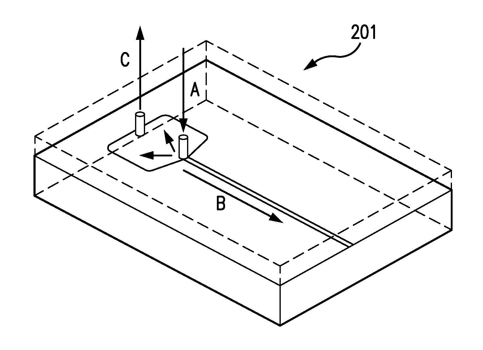
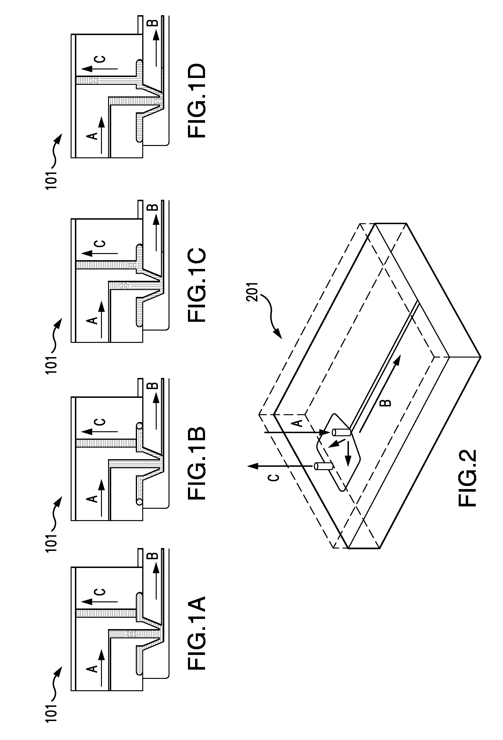
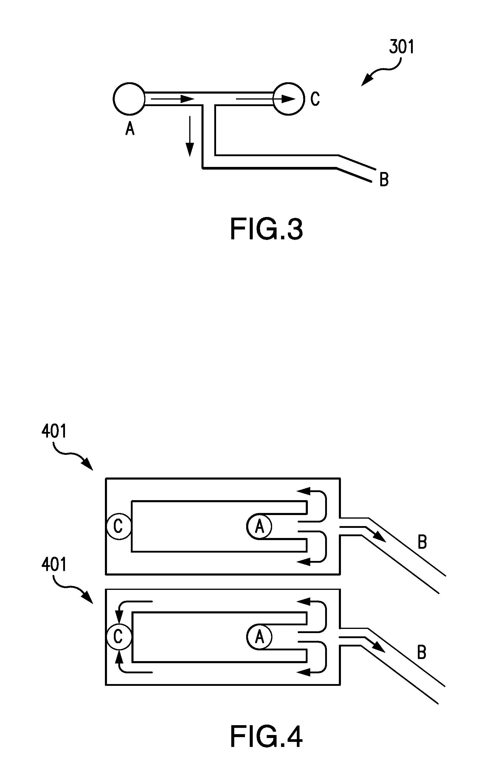
[0033]Embodiments of the systems and methods of creating and moving segmented flows of multiple miscible fluid species through a microfluidic system, while minimizing diffusion effects between the fluid species, are described herein with reference to figures. In the illustrated embodiments, regions of fluid that become diffused during their transport through the microfluidic system are diverted or vented away from a collection or measurement area such that only regions of fluid with no or little diffusion are sent to the collection or measurement area.

[0034]FIGS. 1A-1D illustrate a diffusion minimization system 101 for the elimination and / or minimization of diffusion effects according to one embodiment of the present invention. As shown in FIGS. 1A-D, diffusion minimization system 101 has pathways or channels A-C, which are in fluid communication with each other (i.e., fluid may flow from one of channels A-C into another of channels A-C). In one embodiment, fluid enters the system v...


PUM

PropertyMeasurementUnit
Flow rateaaaaaaaaaa
Volumeaaaaaaaaaa
Areaaaaaaaaaaa

Abstract

The present invention relates to systems and methods for minimizing or eliminating diffusion effects. Diffused regions of a segmented flow of multiple, miscible fluid species may be vented off to a waste channel, and non-diffused regions of fluid may be preferentially pulled off the channel that contains the segmented flow. Multiple fluid samples that are not contaminated via diffusion may be collected for analysis and measurement in a single channel. The systems and methods for minimizing or eliminating diffusion effects may be used to minimize or eliminate diffusion effects in a microfluidic system for monitoring the amplification of DNA molecules and the dissociation behavior of the DNA molecules.

Description

CROSS-REFERENCE TO RELATED APPLICATIONS[0001]This application claims the benefit of U.S. Provisional Patent Application Ser. No. 61 / 168,395, filed on Apr. 10, 2009, which is incorporated herein by reference in its entirety.BACKGROUND[0002]1. Field of the Invention[0003]The present invention relates to systems and methods for minimizing and / or eliminating diffusion effects in a microfluidic system. More specifically, embodiments of the present invention relate to systems and methods for minimizing and / or eliminating diffusion effects in a microfluidic system having one or more channels so that concentration dependent measurements can be made on a segmented flow of multiple miscible fluids in the one or more channels.[0004]2. Description of Related Art[0005]The detection of nucleic acids is central to medicine, forensic science, industrial processing, crop and animal breeding, and many other fields. The ability to detect disease conditions (e.g., cancer), infectious organisms (e.g., H...

Claims


Application Information

Patent Timeline
IPC IPC(8): G01N1/10C12Q1/68C12M1/34
CPCB01L3/502715Y10T436/25B01L2200/0684B01L2200/141B01L2200/147B01L2300/18G01N2035/00544G01N33/50G01N21/66F04B49/106B01L2300/0861B01L2200/10H05B1/025F04B49/065B01L3/502784B01L2300/0816B01L2300/0867C12Q2565/629Y10S435/808Y10S436/805Y10S436/809C12Q1/6806B01L7/525
Inventor MURPHY, BRIANCOREY, SCOTTFLAMM, ALEXLANE, BENLASKOWSKI, CONRADSCHNEIDER, CHAD
Owner CANON US LIFE SCIENCES INC
Learn More