Gas sensor element
- Summary
- Abstract
- Description
- Claims
- Application Information
AI Technical Summary
Benefits of technology
Problems solved by technology
Method used
Image

Examples
first embodiment
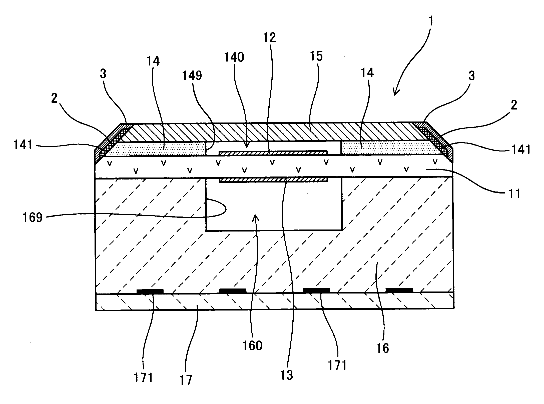
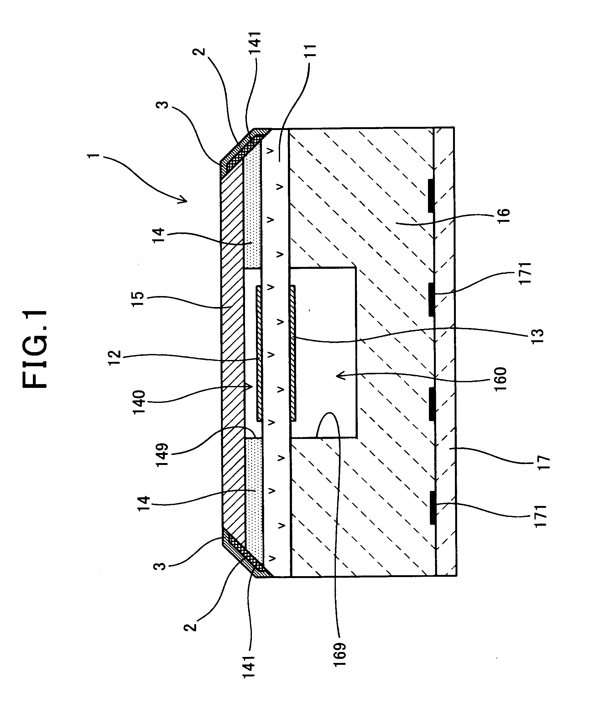
[0055]FIG. 1 shows the overall configuration of a gas sensor element 1 according to the first embodiment of the invention. In the present embodiment, the gas sensor element 1 is configured to be used in an A / F (Air / Fuel) ratio sensor that is disposed in the exhaust system of an internal combustion engine of a motor vehicle to sense the A / F ratio of air-fuel mixture supplied to the engine. More specifically, the A / F sensor determines the A / F ratio based on the limit current flowing between electrodes of the gas sensor element 1; the limit current depends on the concentration of oxygen in the exhaust gas from the engine.
[0056]As shown in FIG. 1, the gas sensor element 1 includes a solid electrolyte body 11, a measurement electrode 12, a reference electrode 13, and a porous diffusion-resistant layer 14. The solid electrolyte body 11 has oxygen ion conductivity and an opposite pair of first and second surfaces (i.e., the upper and lower surfaces in FIG. 1). The measurement electrode 12 ...
modification 1
[Modification 1]
[0083]In the previous embodiment, as shown FIG. 1 both the trap layer 2 and the protective layer 3 are formed only to cover the outer side surface 141 of the porous diffusion-resistant layer 14.
[0084]However, as shown in FIG. 4, it is also possible to form both the trap layer 2 and the protective layer 3 to extend over the entire outer periphery 100 of the gas sensor element 1.
[0085]In addition, though not graphically shown, it is also possible to form only one of the trap layer 2 and the protective layer 3 to extend over the entire outer periphery 100 of the gas sensor element 1 while forming the other only to cover the outer side surface 141 of the porous diffusion-resistant layer 14.
modification 2
[Modification 2]
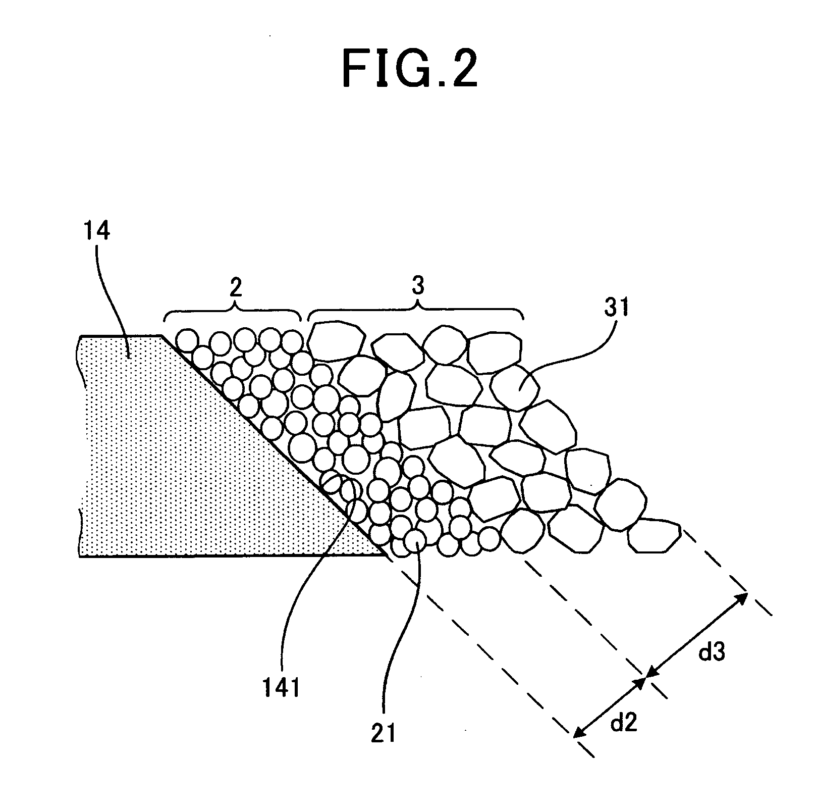
[0086]In the previous embodiment, as shown in FIG. 1, there is interposed the trap layer 2 between the outer side surface 141 of the porous diffusion-resistant layer 14 and the protective layer 3.
[0087]However, as shown in FIG. 5, it is also possible to omit the trap layer 2 from the gas sensor element 1, forming the protective layer 3 directly on the outer side surface 141 of the porous diffusion-resistant layer 14.
PUM
 Abstract
Description
Claims
Application Information
PatSnap Eureka turns technology decisions into work you can execute. Powered by our Innovation Knowledge Graph, it runs expert workflows across engineering, life sciences, materials and intellectual property. Get your review-ready output in minutes.


