
Sensor element

Pending Publication Date: 2021-07-08
NGK INSULATORS LTD
View PDF0 Cites 0 Cited by
  • Summary
  • Abstract
  • Description
  • Claims
  • Application Information

AI Technical Summary

Benefits of technology

This patent is about a gas sensor that detects a specific gas component in a measurement gas. The invention prevents water-induced cracking of the sensor element and increases its resistance to water. The result is a sensor element that is more durable and better equipped to resist damage from water than previous versions.

Problems solved by technology

The sensor element according to Japanese Patent Application Laid-Open No. 2016-48230, however, does not necessarily have sufficient water resistance property, and is subject to water-induced cracking in a case where the amount of water exposure is large.
In the gas sensor element disclosed in Japanese Patent No. 6014000 in which the second protective layer on the outer side covers the whole first protective layer on the inner side, a porosity of the second protective layer is small, thus there is a possibility that the second protective layer is peeled off on the back end side due to insufficient adhesion to an element body or water-induced cracking occurs in use at a high temperature.

Method used


Image

  • Sensor element
  • Sensor element
  • Sensor element

Examples


first embodiment

[0021]

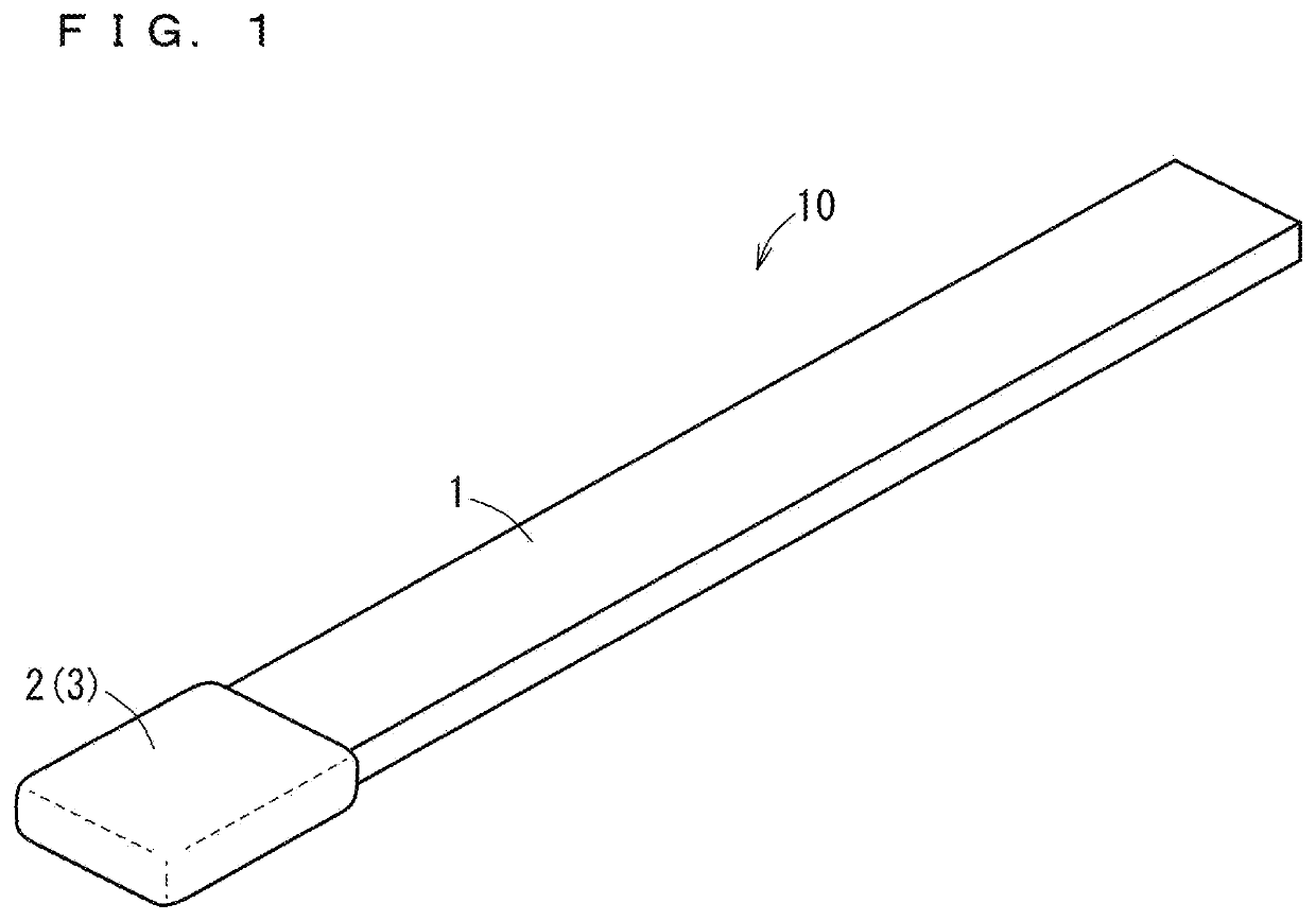
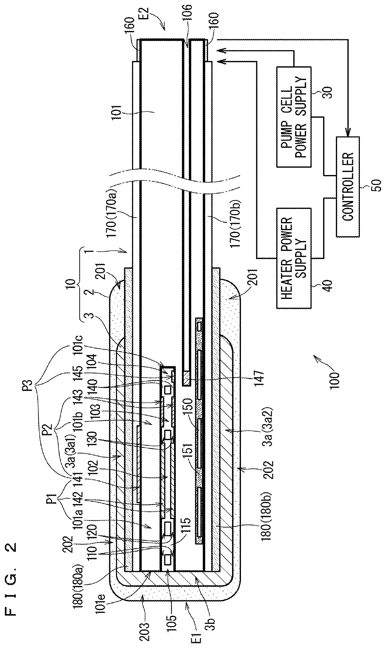
[0022]FIG. 1 is a schematic external perspective view of a sensor element (gas sensor element) 10 according to a first embodiment of the present invention. FIG. 2 is a schematic diagram illustrating a configuration of a gas sensor 100 including a sectional view taken along a longitudinal direction of the sensor element 10. The sensor element 10 is a main component of the gas sensor 100 detecting a predetermined gas component in a measurement gas, and measuring concentration thereof. The sensor element 10 is a so-called limiting current gas sensor element.

[0023]The gas sensor 100 mainly includes a pump cell power supply 30, a heater power supply 40, and a controller 50 in addition to the sensor element 10.

[0024]As illustrated in FIG. 1, the sensor element 10 schematically has a configuration that a side of one end portion of an elongated planar element base 1 is covered by a porous outer leading-end protective layer (first leading-end protective layer) 2 and an intermediate lea...

second embodiment

[0108]The configuration of the sensor element for securing water resistance property by interposing the intermediate leading-end protective layer between the outer leading-end protective layer and the element base while suppressing delamination and detachment of the outer leading-end protective layer is not limited to that shown in the first embodiment. In the present embodiment, a configuration of a sensor element 20 heated in accordance with a temperature profile shifted to a lower temperature side compared with the sensor element 10 according to the first embodiment is described.

[0109]FIG. 6 is a sectional view taken along the longitudinal direction of the sensor element 20 according to a second embodiment of the present invention. The sensor element 20 has components similar to those of the sensor element 10 according to the first embodiment except for some components. The similar components thus bear the same reference signs as those in the first embodiment, and detailed descri...

modification example

[0129]The above-mentioned embodiments are targeted at a sensor element having three internal chambers, but the sensor element may not necessarily have a three-chamber configuration. That is to say, the configuration in which the inner leading-end protective layers having a large porosity are provided on outermost surfaces of the element base on the end portion at least including the gas distribution part, and, further, the outer leading-end protective layer as the porous layer having a smaller porosity than the inner leading-end protective layers is provided outside the inner leading-end protective layers so that the intermediate leading-end protective layer is interposed between the outer leading-end protective layer and the portion of the element base in which the temperature becomes 500° C. or more during use is applicable to a sensor element having one internal chamber or two internal chambers.

[0130]In the above-mentioned embodiments, the region heated to a temperature of 500° C...


PUM

PropertyMeasurementUnit
Temperatureaaaaaaaaaa
Fractionaaaaaaaaaa
Fractionaaaaaaaaaa

Abstract

A sensor element includes: an inner protective layer having a porosity of 30% to 65% on two main surfaces; an intermediate protective layer, at least a part of which has contact with the inner layer, and having a porosity of 25% to 80%, which is equal to or smaller than the porosity of the inner layer; and an outer protective layer surrounding an element base on an outermost periphery on the one end portion of the sensor element, having contact with the intermediate and the inner layer, having contact with a leading end surface of the element base or the intermediate layer on the leading end surface, and having a porosity of 15% to 30%, which is smaller than the porosity of the intermediate layer, wherein a difference of porosity between the inner and the outer layer is 10% to 50%.

Description

CROSS-REFERENCE TO RELATED APPLICATION[0001]This application is a continuation application of PCT / JP2019 / 037894, filed on Sep. 26, 2019, which claims the benefit of priority of Japanese Patent Application No. 2018-187834, filed on Oct. 3, 2018, the entire contents of which are incorporated herein by reference.BACKGROUND OF THE INVENTIONField of the Invention[0002]The present invention relates to a gas sensor detecting a predetermined gas component in a measurement gas, and, in particular, to a configuration for preventing water-induced cracking of a sensor element included in the gas sensor.Description of the Background Art[0003]As a gas sensor for determining concentration of a desired gas component in a measurement gas, a gas sensor that includes a sensor element made of an oxygen-ion conductive solid electrolyte, such as zirconia (ZrO2), and including some electrodes on the surface and the inside thereof has been widely known. Such a sensor element includes a protective layer for...

Claims


Application Information

Patent Timeline
IPC IPC(8): G01N27/407C04B38/00G01N27/41G01N27/419
CPCG01N27/4077C04B38/00G01N27/4071G01N27/41G01N27/419G01N27/4078C04B38/0074C04B35/10
Inventor WATANABE, YUSUKEKAI, MIKAONISHI, RYOSUZUKI, SAKIHINO, TAKASHI
Owner NGK INSULATORS LTD
Features
  • Generate Ideas
  • Intellectual Property
  • Life Sciences
  • Materials
  • Tech Scout
  • Unparalleled Data Quality
  • Higher Quality Content
  • 60% Fewer Hallucinations
Learn More