Light emitting module

Inactive Publication Date: 2011-04-28
PANASONIC CORP
View PDF6 Cites 17 Cited by
  • Summary
  • Abstract
  • Description
  • Claims
  • Application Information

AI Technical Summary

Benefits of technology

[0016]With such configuration, it is possible to three-dimensionally arrange the electric connection members in the thickness direction of the light emitti

Problems solved by technology

Thus, the lead lines tend to catch the user's eye and provide undesirable outward appearance if the light emitting module is used as, e.g., a display or an indoor illum

Method used


Image

  • Light emitting module
  • Light emitting module
  • Light emitting module

Examples


Example

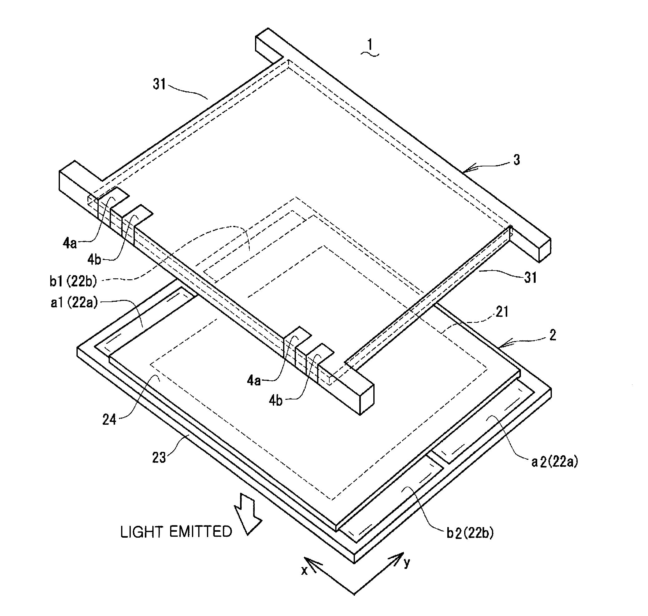
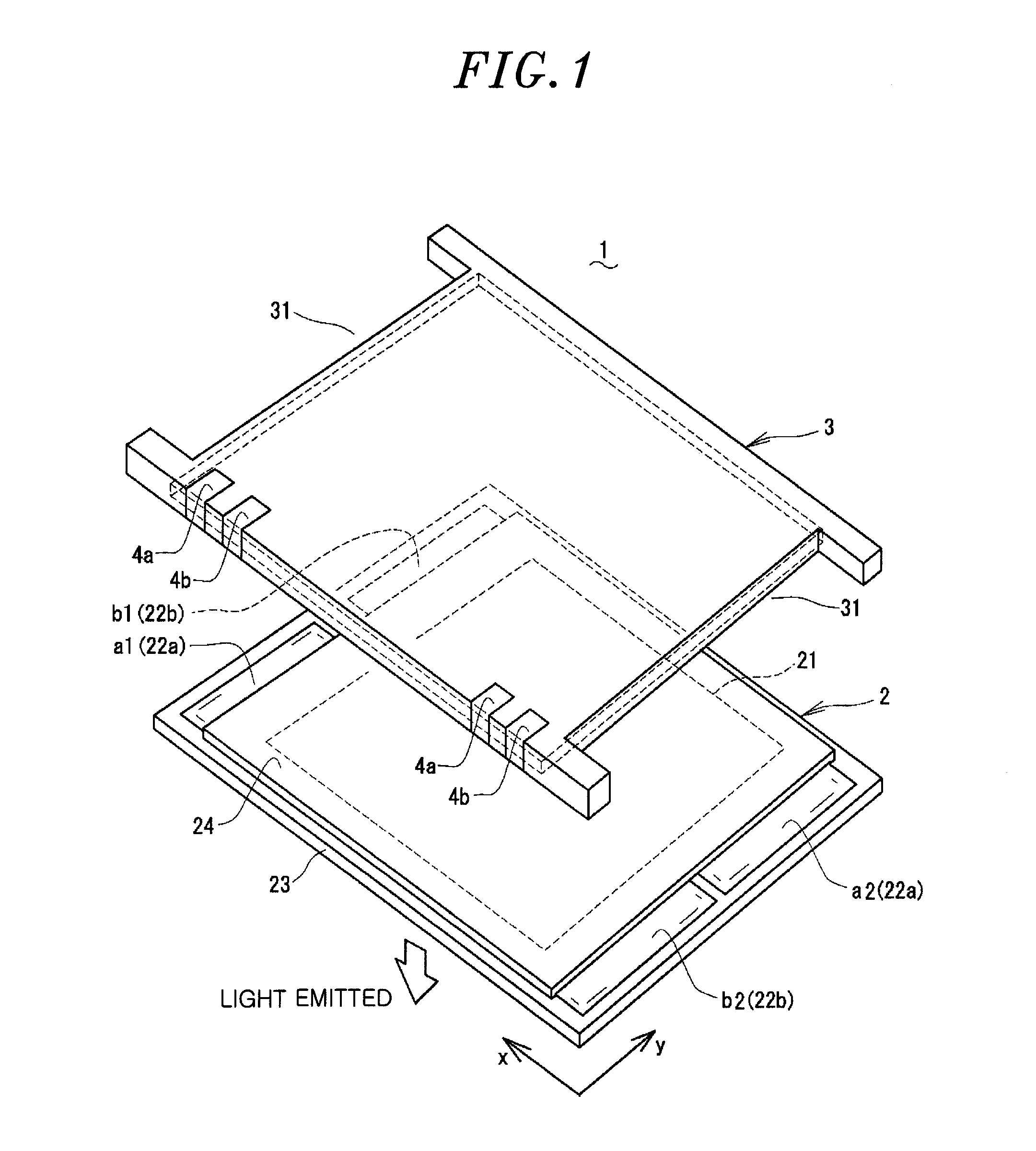
[0029]A light emitting module in accordance with a first embodiment of the present invention will be described with reference to FIGS. 1 through 3. As shown in these drawings, the light emitting module 1 includes a plate-shaped organic EL light emitting element (hereinafter referred to as “light emitting element”) 2, a support body 3 for supporting the light emitting element 2, and power feeding terminals 4a and 4b provided in the support body 3 for feeding electric power to the light emitting element 2. The light emitting module 1 emits light from one side (light emitting surface) of the light emitting element 2 from the side supported by the support body 3. In the following description, the direction designated by “x” will be defined as the left-right direction of the light emitting module 1 and the direction designated by “y” as the front-rear direction of the light emitting module”.

[0030]The light emitting element 2 includes a light emitting layer 21 (the hatched portion in FIG....

Example

Second Embodiment

[0045]A light emitting module in accordance with a second embodiment of the present invention will be described with reference to FIGS. 4 and 5. As shown in these drawings, each of the openings 31 of the support body 3 employed in the light emitting module 1 of the present embodiment is formed into a rectangular shape at the opposite lateral sides of the support body 3 and is provided with a partition portion 32 for partitioning the mutually adjoining power feeding electrodes a1 and b1 of different polarities and the mutually adjoining power feeding electrodes a2 and b2 of different polarities. This provides independent openings in a corresponding relationship with the power feeding electrodes a1 and b1 and the power feeding electrodes a2 and b2. Other configurations remain the same as above.

[0046]With the light emitting module 1 of the present embodiment, each of the openings 31 is partitioned in a corresponding relationship with the mutually adjoining power feedin...

Example

Third Embodiment

[0047]A light emitting module in accordance with a third embodiment of the present invention will be described with reference to FIGS. 6 through 9. As shown in FIGS. 6 and 7, the light emitting module 1 of the present embodiment is a circuit-incorporating light emitting module that includes a circuit board making up a power supply circuit for generating a regulated direct current to be supplied to the light emitting element 2 and / or a control circuit for controlling the electric power to be supplied to the light emitting element 2. The circuit board 6 is arranged at one lateral side of the light emitting element 2 and installed on the side of the support body 3 at which the light emitting element 2 exists. On the upper surface of the circuit board 6, there are provided left and right power feeding terminals 4a and 4b connected to the power feeding electrodes a1, a2, b12 and b22 of the light emitting element 2 and external terminals 61a and 61b connected to the left a...


PUM


Abstract

A light emitting module includes an organic EL light emitting element and a support body supporting the organic EL light emitting element. The support body is attached to the organic EL light emitting element at the side of the non-light emitting surface of the light emitting module to cover one surface of the organic EL light emitting element. The organic EL light emitting element includes power feeding electrodes. The support body includes openings formed in a corresponding relationship with the power feeding electrodes. The power feeding electrodes exposed on the non-light emitting side of the support body through the openings. The support body includes power feeding terminals. The power feeding terminals partially exposed on the non-light emitting side of the support body. The power feeding terminals electrically connected to the power feeding electrodes by electric connection members extending via the non-light emitting side and the openings of the support body.

Description

FIELD OF THE INVENTION[0001]The present invention relates to a light emitting module provided with an organic electroluminescence (hereinafter referred to as “EL”) light emitting element.BACKGROUND OF THE INVENTION[0002]Conventionally, there is known a light emitting module that includes an organic EL light emitting element (hereinafter referred to as “light emitting element”), a support body for supporting the light emitting element at the opposite side from the light emitting surface and a power feeding terminals provided in the support body for feeding electric power to the light emitting element (see, e.g., Japanese Patent Application Publication No. 2007-529177). The power feeding terminals are current supplying electrodes electrically connected to the element electrodes of the light emitting element and are arranged in, e.g., an element control circuit board held by the support body.[0003]In the conventional light emitting module mentioned above, however, lead lines for interc...

Claims


Application Information

Patent Timeline
IPC IPC(8): H05B37/02H01J1/62
CPCF21Y2105/008H01L2251/5361H01L51/5237H01L51/5203F21Y2105/00F21Y2115/15H01L2924/19107H10K50/805H10K50/84H10K50/841
Inventor TANAHASHI, OSAMUFUKANO, SATOSHIHAYASHI, SHINTAROUANAMI, SHINICHISUMIYAMA, SHIGETSUGUSAIMI, MOTOHIROKAWACHI, HIDEHARU
Owner PANASONIC CORP
Why Eureka
Try Eureka