Probe card

Inactive Publication Date: 2011-04-28
MICROELECTRONICS TECH INC
View PDF7 Cites 19 Cited by
  • Summary
  • Abstract
  • Description
  • Claims
  • Application Information

AI Technical Summary

Benefits of technology

[0006]From the above, the transmitting distance for the test signals to the tip of the probe is longer in the conventional probe cards. Therefore, one aspect of the present invention is to provide a prob

Problems solved by technology

However, the complexity of the transmitting lines in the probe card has led to the overall transmitting distance for the test signals becoming longer.
Therefore, the loss or distortion of the test signals received by the device under test is usually caused by the multi-layered structure of the probe card, the exceeding length of the transmitting distance, or the interference from the ground wire.
For the same or similar reason, the tes

Method used


Image

  • Probe card
  • Probe card
  • Probe card

Examples


Example

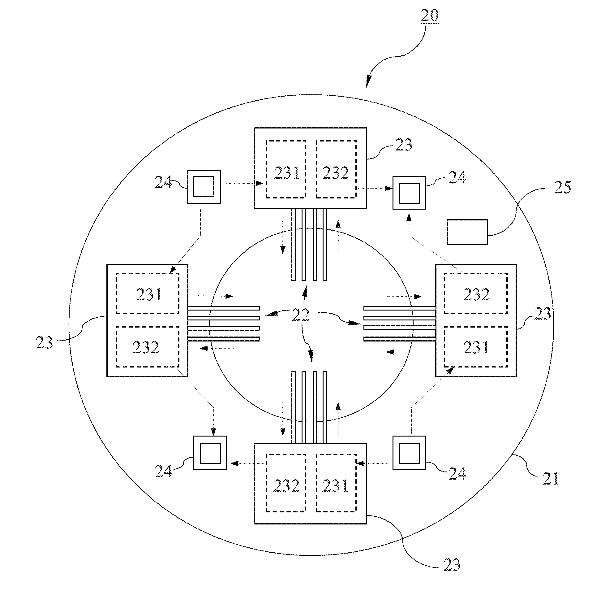
[0016]In a conventional probe card, after being transmitted from the tester, the test signals would pass through a multi-layered structure of the probe card having a relatively long distance, and then arrive at the tips of the probes. Besides the contribution by the conductive lines distance, the influence due to the connection methods and the ground lines also cause the loss or distortion of the test signals. In order to resolve these problems, the probe assembly and the capability of signal processing (including the generation and transmission of test signals) are detached or separated from the other parts of the probe card, and is being combined together as a probe system module. In response to the control signals from the tester, the probe system module itself generates test signals. As a result, the transmitting distance to the tips of the probes is thereby minimized.

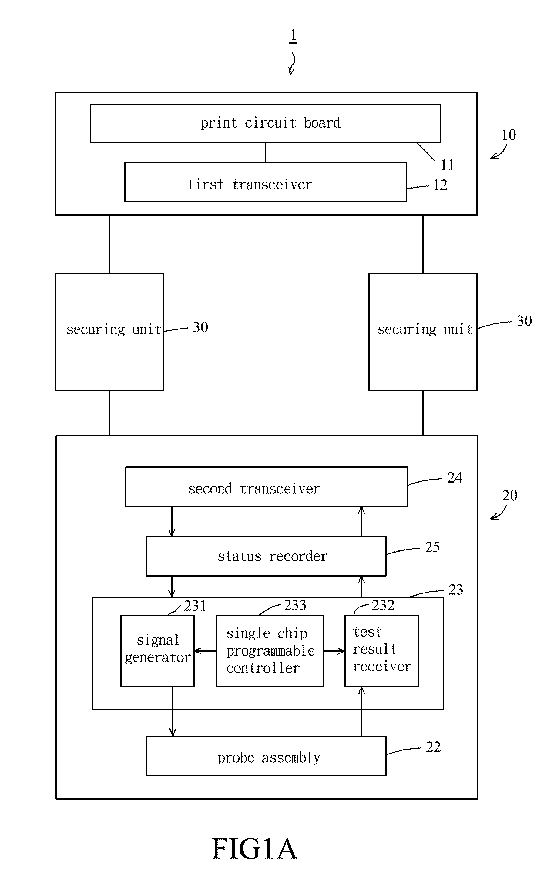
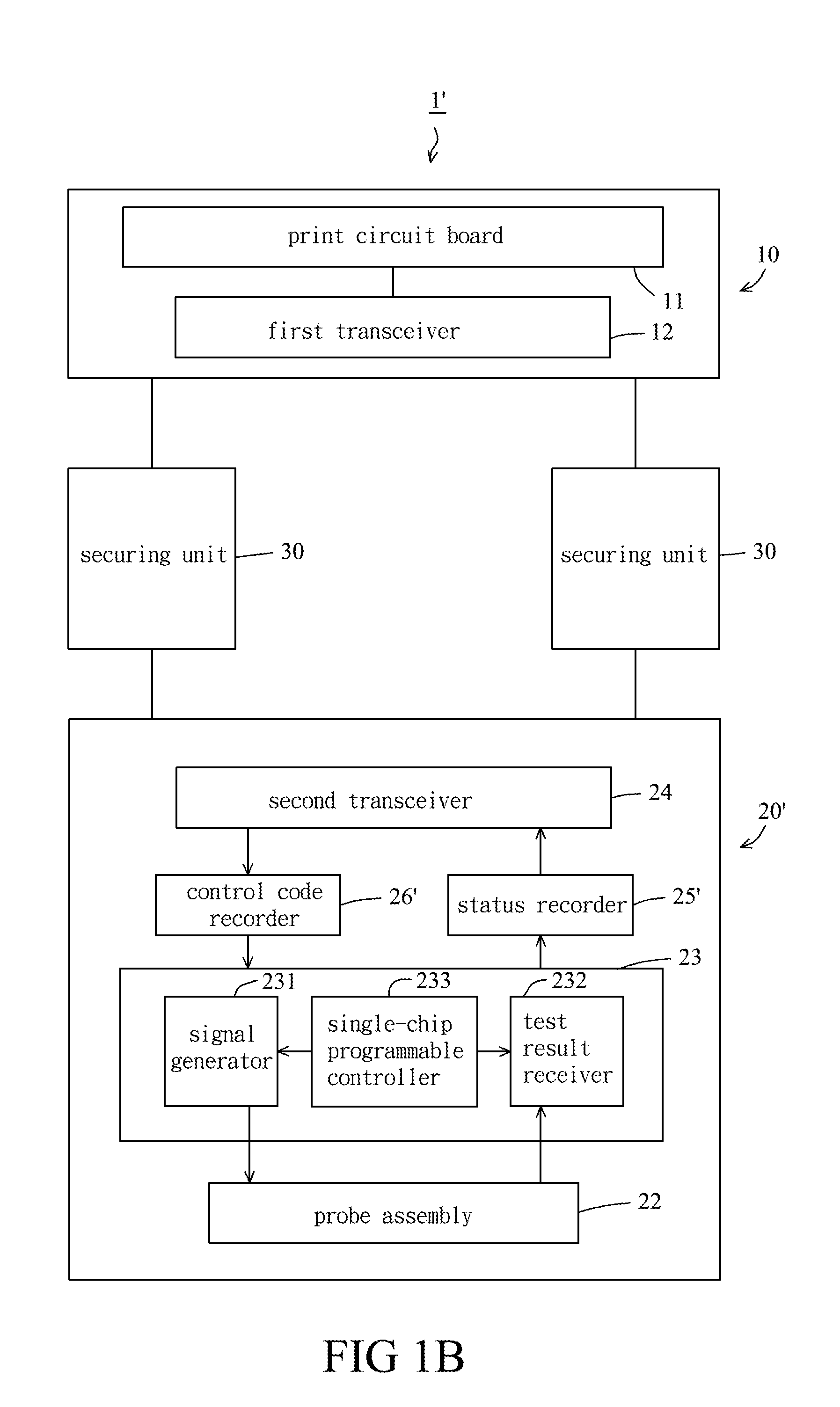
[0017]Please refer to FIG. 1A and FIG. 2. FIG. 1A and FIG. 2 show a system architecture diagram and a schematic ...


PUM


Abstract

A probe card is provided. The probe card detaches or separates a probe assembly and a test signal generator which generates test signals from the tester and the printed circuit board, so as to form a probe system module. The probe system module is secured into a probe card module by one or more securing unit. The probe card module includes the printed circuit board. Control signals from the tester are wirelessly transmitted to the probe system module and drive the probe system module to generate the corresponding test signals. Therefore, the loss or distortion of the test signals due to having longer transmitting distances will be reduced and thus the test quality can be improved.

Description

FIELD OF INVENTION[0001]The invention relates to a probe card, and especially relates to a probe card which has a probe system module able to maintain signal integrity of the test signals.BACKGROUND OF THE INVENTION[0002]During a wafer testing, the tester, which communicates with a wafer through a probe card, transmits test signals to the wafer and then gets response signals from the wafer. Generally speaking, the probe card includes a plurality of precise probes. During the test, by means of the precise probes contacting with the small pads or bumps on a device under test (DUT), the test signals are transmitted from the tester to the device under test, and with the coordination of the control procedures of the probe card and the tester, the testing or measuring is thereby completed.[0003]With improvements in technology, the structure of the probe card has become more precise and sophisticated. However, the complexity of the transmitting lines in the probe card has led to the overal...

Claims


Application Information

Patent Timeline
IPC IPC(8): G01R31/00
CPCG01R31/3025
Inventor CHOU, YOUNG HUANGKU, WEI CHENG
Owner MICROELECTRONICS TECH INC
Why Eureka
Try Eureka