
Music-visualizer system and methods

a music visualizer and music technology, applied in the field of music visualizer systems and methods, can solve the problems of not being able to combine rendering and animation in the music visualizer application for embeddable platforms, the current related art is not known to use shader-based methods for music visualization, and the low power of embedded platforms. achieve the effect of enhancing the musical listening experience, accurate representation in the visual representation, and sufficient cpu capacity

Inactive Publication Date: 2011-04-28
SONY CORP +1
View PDF4 Cites 32 Cited by
  • Summary
  • Abstract
  • Description
  • Claims
  • Application Information

AI Technical Summary

Benefits of technology

The present invention is a system and method for visualizing music using a graphics processing unit (GPU) and a custom shader software program. The system can be embedded in a television platform or a set-top box platform, providing a unique audiovisual experience for users. The method involves converting waveform data to geometry data, recognizing and accepting the data, and rendering a plurality of graphical images that correspond to the music being played. The system can provide a simulated synesthetic experience for non-synesthetes, allowing them to visualize the music in real-time. The technical effects of the invention include enhancing the musical experience for all users and providing a high-density resolution graphical representation of the music.

Problems solved by technology

This related art approach works well on powerful personal computer (PC) platforms having substantial processing power, but the related art approach is not amenable to low power embedded platforms.
Currently, the related art is not known to combine rendering with animation in a music-visualizer application for an embeddable platform, e.g., a television device, a set-top box device, and a hand-held device.
Further, the current related art is not known to use shader-based methods for music visualization, especially with television or set-top box platforms.

Method used


Image

  • Music-visualizer system and methods
  • Music-visualizer system and methods
  • Music-visualizer system and methods

Examples


Embodiment Construction

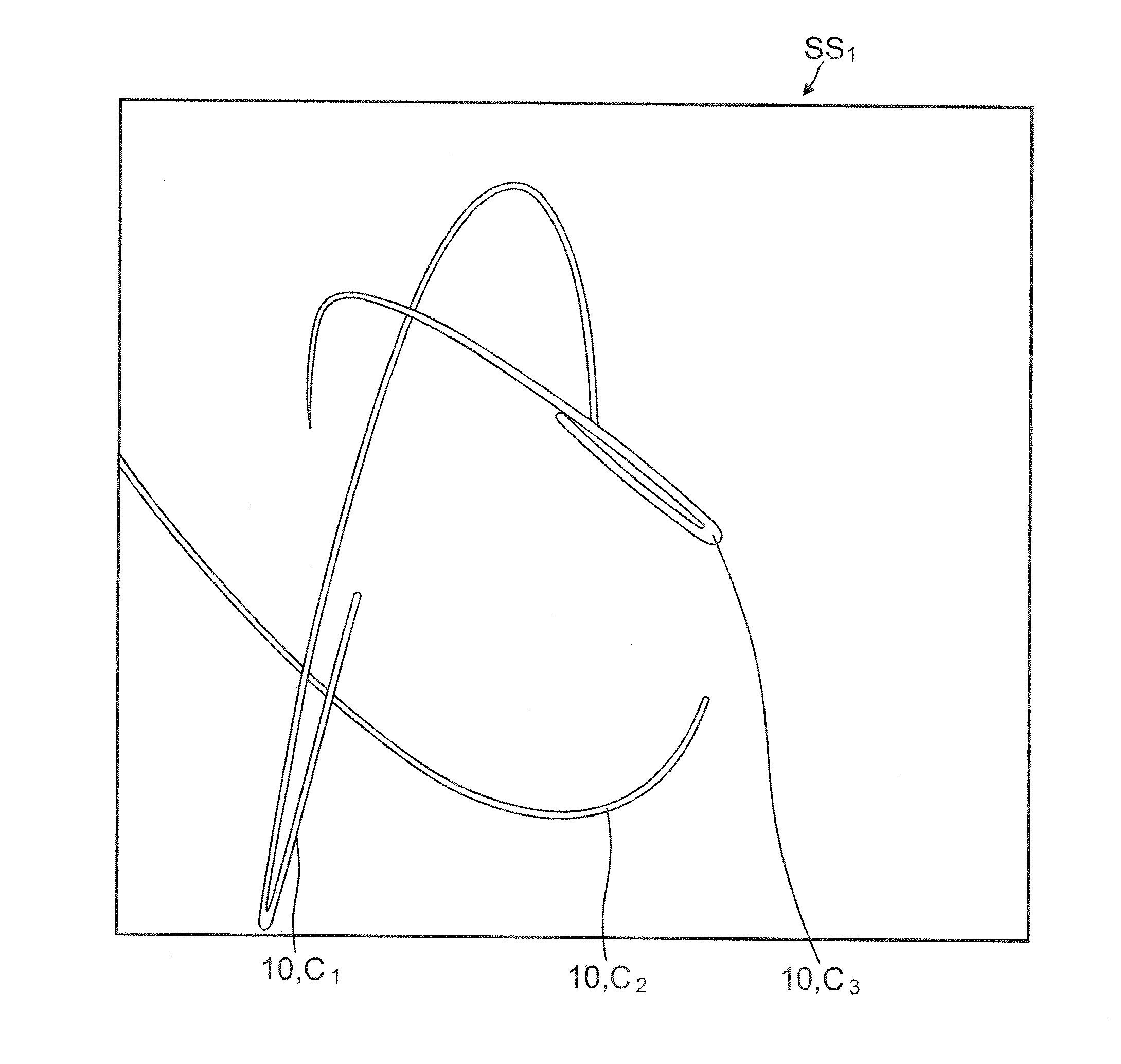
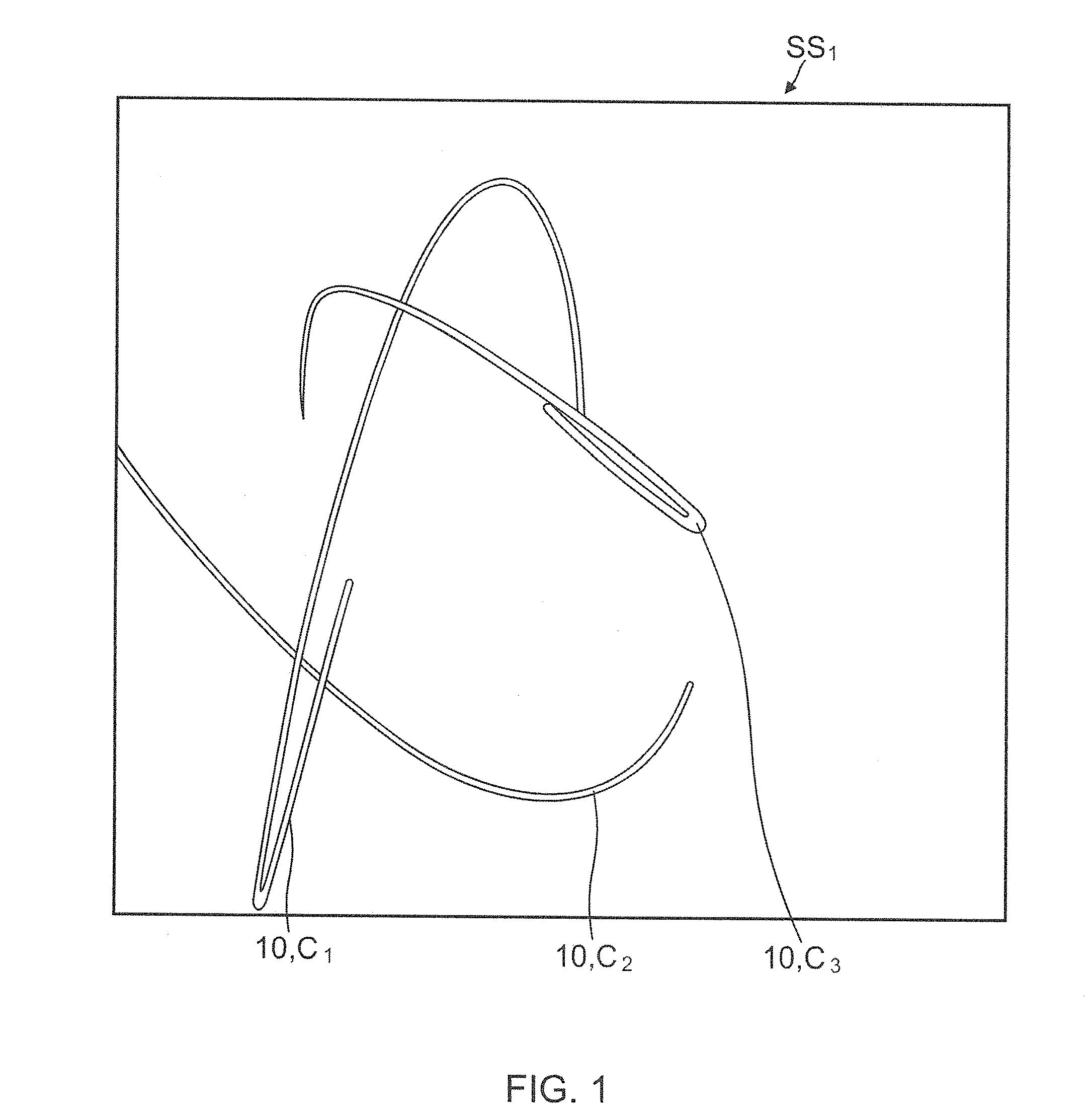
[0017]FIG. 1, illustrates, in a screen shot SS1, a display generated by a music visualizer system, showing a visual representation comprising a plurality of moving linear elements 10 having a corresponding plurality of colors C1, C2, C3, by example only, according to an embodiment of the present invention. The present system utilizes at least one custom shader software program for both rendering as well as animation calculations. Since music visualization tasks for embedded platforms are CPU-intensive, low power CPUs are not equipped to decode music as well as perform complex animations simultaneously as would otherwise be required for more interesting accurate real-time music visualizations. By merging the animation calculation into the rendering pipeline, the present system off-loads tasks, otherwise performed by a CPU, onto the GPU for handling the bulk of the visualization processing, thereby providing sufficient capacity in the CPU for extensive decoding of the music. By off-lo...


PUM


Abstract

A music visualization system and methods involving a central processing unit capable of converting waveform data to geometry data, a graphics processing unit capable of recognizing and accepting the geometry data and rendering a plurality of graphical images, a custom shader software program being operable on the graphics processing unit, an embeddable platform being in electronic communication with the graphics processing unit, and an audiovisual display device in electronic communication with the graphics processing unit and the embeddable platform.

Description

TECHNICAL FIELD[0001]The present invention technically relates to systems and methods for visualizing music. More particularly, the present invention technically relates to systems and methods for visualizing music on a graphic display. Even more particularly, the present invention technically relates to systems and methods for visualizing music on a graphic display by way of an embeddable platform.BACKGROUND ART[0002]Music-visualizers have become an integral part of the music listening experience and a mainstay for most media devices. However, most related art music-visualizers use a repeating, or a semi-repeating, pattern of colors, movement, or shapes to provide an abstract interpretation of music being played. These visualizers usually typically run “canned” complex animation algorithms or “canned” mathematical formulas on a central processing unit (CPU), akin to what can be seen on computer screen-savers. This related art approach works well on powerful personal computer (PC) p...

Claims


Application Information

Patent Timeline
Patent Type & Authority Applications(United States)
IPC IPC(8): G06T15/50G06F17/00G06F3/048
CPCG06T2210/56G06T15/005G10H1/368G10H2220/005
Inventor ADHIKARI, SURANJITHSIAO, ERIC
Owner SONY CORP
Learn More