Temperature detecting device for motion guide apparatus

a technology of temperature detection device and motion guide apparatus, which is applied in the direction of heat measurement, instruments, gearing, etc., can solve the problems of generating a great heat, affecting the operation of the motion guide apparatus, and having a good chance of breaking or damage to the cartridge, etc., to prevent the motion guide apparatus from overheating.

Inactive Publication Date: 2011-04-28
HIWIN TECH
View PDF6 Cites 27 Cited by
  • Summary
  • Abstract
  • Description
  • Claims
  • Application Information

AI Technical Summary

Benefits of technology

The primary objective of the present invention is to provide a motion guide apparatus including two movable members movable relative to each other, and a temperature detecting device attached to one of the two movable members for detecting the temperature of the motion guide apparatus and for preventing the motion guide apparatus from overheating.

Problems solved by technology

However, the cartridge may have a good chance to be broken or damaged after use, but may not be easily and quickly changed or replaced with the other new ones because the cartridge is deeply received or engaged in the monitoring device and may not be easily disengaged from the thermal limit value pickup or device and thus may not be easily repaired.
Typical motion guide apparatuses, such as the linear motion guide apparatuses or the ball screw devices comprise two movable members rotatable or movable relative to each other, and a number of ball bearing elements disposed between the two movable members for facilitating the sliding movement between the two movable members and may generate a great heat when the two movable members are rotated relative to each other in a great rotational speed.
However, no temperature detecting devices have been developed and provided and attached to one of the two movable members for detecting the temperature of the motion guide apparatus, and a great heat may be generated between the movable members and the ball bearing elements, such that the users may not aware the temperature of the movable members and may not prevent the motion guide apparatus from overheating.

Method used


Image

  • Temperature detecting device for motion guide apparatus
  • Temperature detecting device for motion guide apparatus
  • Temperature detecting device for motion guide apparatus

Examples


Embodiment Construction

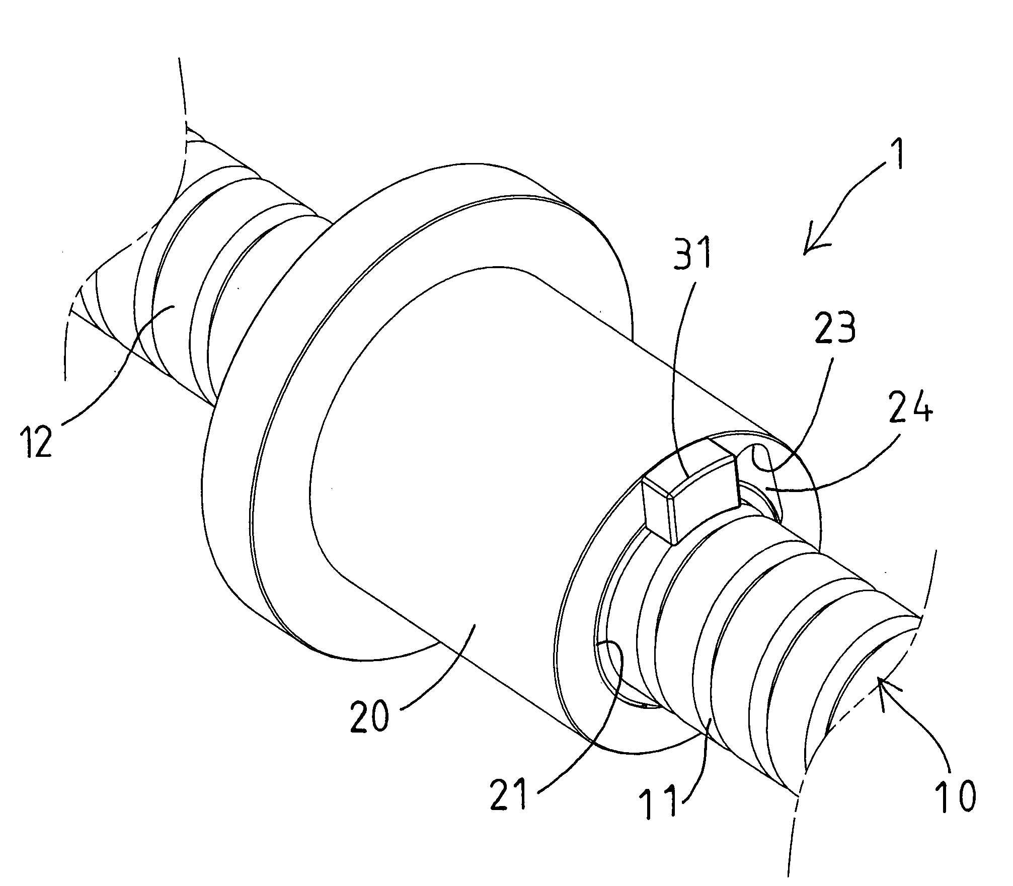
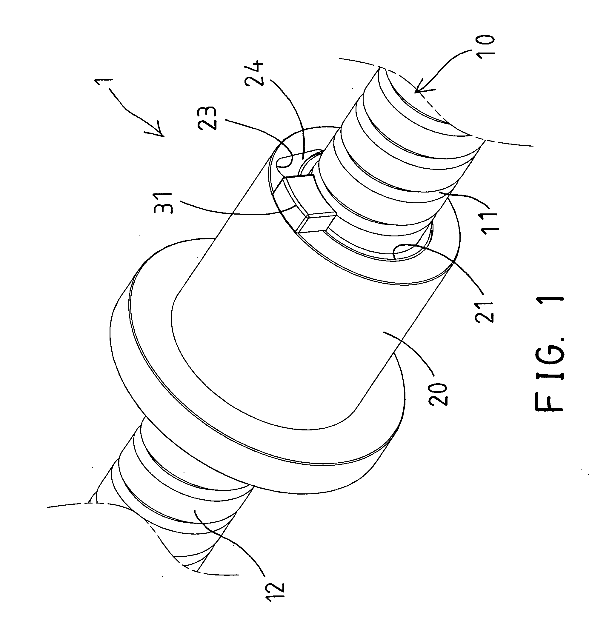
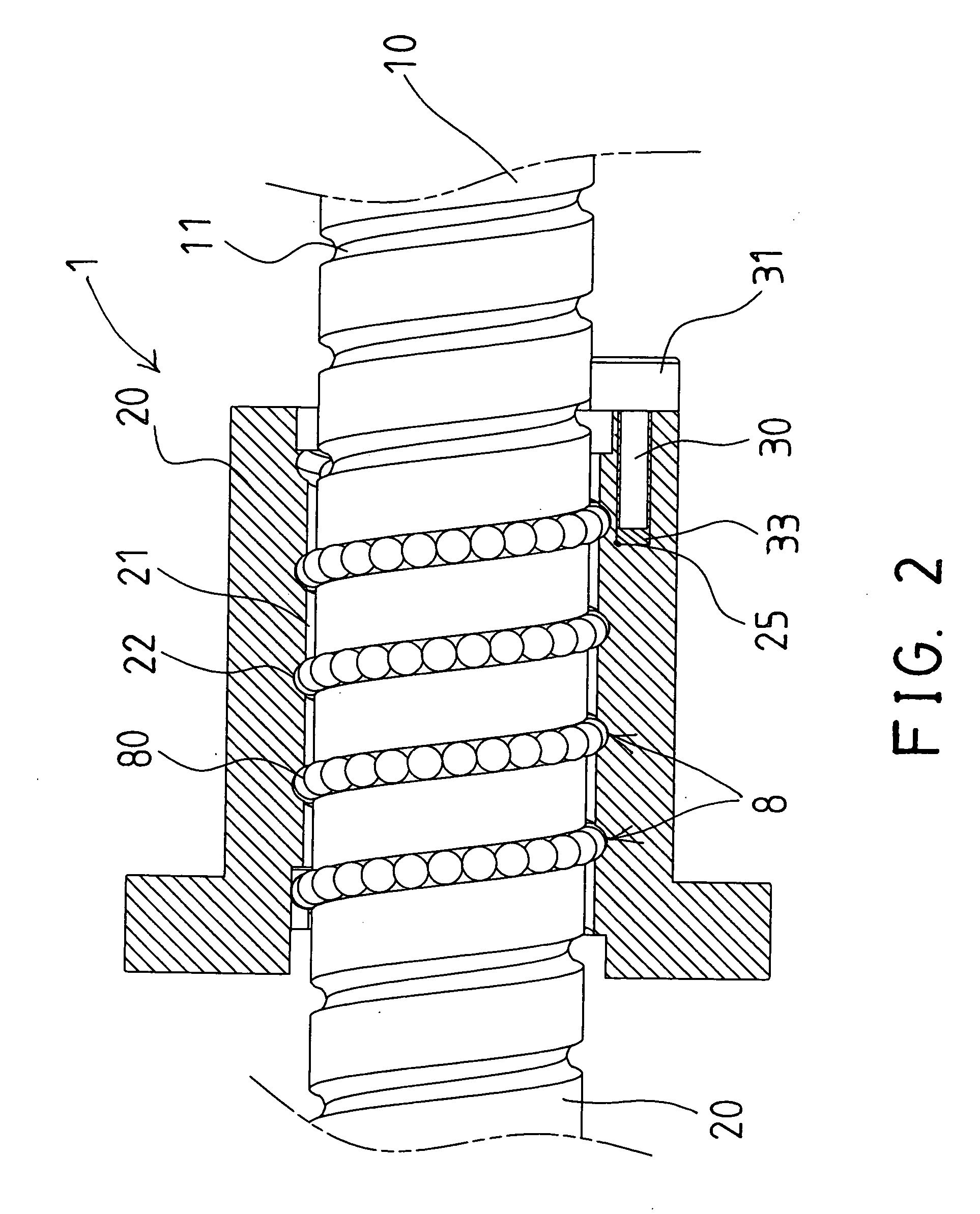
Referring to the drawings, and initially to FIGS. 1-2, a motion guide apparatus 1 in accordance with the present invention, such as a ball screw device 1, comprises an elongated bolt or screw shaft 10 including a number of helical threaded portions or grooves 11 formed on the outer peripheral portion thereof, or formed in the outer peripheral surface 12 thereof, and a movable member, such as a ball nut 20 including a screw hole or bore 21 formed therein for receiving or engaging with the elongated screw shaft 10, and the screw hole or bore 21 of the ball nut 20 is formed or defined by a number of helical threaded portions or grooves 22 for threading or engaging or aligning with the helical threaded portions or grooves 11 of the screw shaft 10, and for forming an endless multiple-turn, helical raceway or ball guiding passage 8 between the screw shaft 10 and the ball nut 20, and for slidably receiving a number of ball bearing elements 80 and for facilitating the sliding or rotational ...


PUM

PropertyMeasurementUnit
temperatureaaaaaaaaaa
heat conductiveaaaaaaaaaa
rotational speedaaaaaaaaaa

Abstract

A motion guide device includes a ball nut attached onto a shaft and having helical grooves for receiving a number of ball bearing elements, and having a compartment form receiving a temperature detecting device which detects a temperature of the ball nut for preventing the ball nut from overheating, an indicating device is coupled to the temperature detecting device for generating an indicating signal when the temperature detecting device has sensed or detected that the temperature of the ball nut or the screw shaft is higher than the predetermined temperature or value, and the user may then stop working to find out what problems have been happened and thus to prevent the motion guide device from overheating.

Description

BACKGROUND OF THE INVENTION1. Field of the InventionThe present invention relates to a motion guide apparatus, such as a linear motion guide apparatus or a ball screw device, and more particularly to a motion guide apparatus including two movable members or a screw shaft and a ball nut movable relative to each other, and a temperature detecting device attached to one of the two movable members for detecting the temperature of the motion guide apparatus and for preventing the motion guide apparatus from overheating.2. Description of the Prior ArtTypical working machines, such as rolling mills comprise a roll bearing engaged in a work roll of a roll stand for directly measuring the temperature at the bearing without detaching connecting lines during changing of rolls.For example, U.S. Pat. No. 4,939,920 to Stahl discloses one of the typical monitoring devices for roll bearings in rolling mills and comprising a monitoring device installed in the chock of the work roll of a roll stand, ...

Claims


Application Information

Patent Timeline
Patent Type & Authority Applications(United States)
IPC IPC(8): G01K1/00F16H25/22G01K7/00G01K7/02
CPCF16H25/2021Y10T74/18576G01K13/08F16H25/2204
Inventor HWANG, YIH CHYUNHUANG, FU-CHUN
Owner HIWIN TECH
Why Eureka
Try Eureka