Interpolation of video compression frames

a video compression and interpolation technology, applied in the field of video compression, can solve the problems of large amount of motion change between p (or i) frames, the ultimate limit of the number of intermediate b frames, and the efficiency and coding range limitations of motion vectors, so as to improve the image quality of one or more predicted frames

Inactive Publication Date: 2011-04-28
DOLBY LAB LICENSING CORP
View PDF89 Cites 17 Cited by
  • Summary
  • Abstract
  • Description
  • Claims
  • Application Information

AI Technical Summary

Benefits of technology

Aspects of the invention are directed to a method, system, and computer programs for improving the image quality of one or more predicted frames in a video image compression system, where each frame comprises a plurality of pixels.

Problems solved by technology

The background may move, but a great deal of the scene often is redundant.
The main limitation in restricting the value of M, and therefore the number of sequential B frames, is that the amount of motion change between P (or I) frames becomes large.
Thus, the efficiency and coding range limitations of motion vectors create the ultimate limit on the number of intermediate B frames.
Thus, any bits used to create B frames are used only for that frame, and do not provide corrections that aid decoding of subsequent frames, unlike P frames.

Method used


Image

  • Interpolation of video compression frames
  • Interpolation of video compression frames
  • Interpolation of video compression frames

Examples


example embodiment

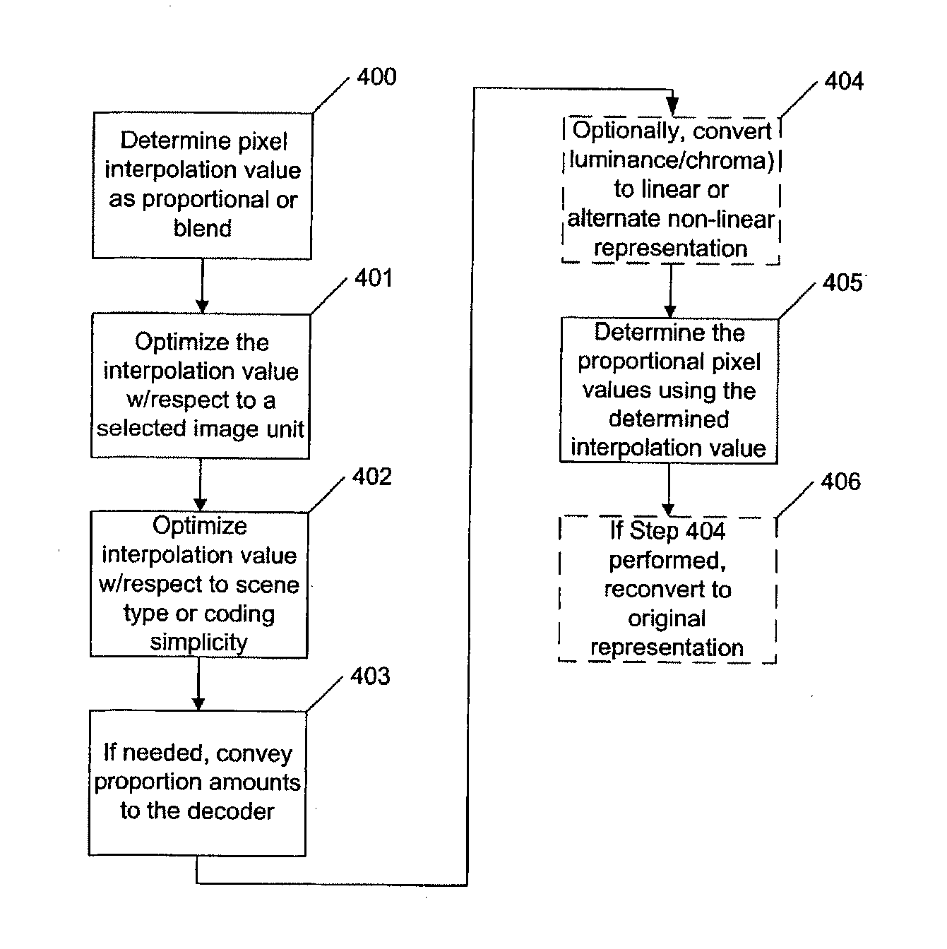
FIG. 4 is a flowchart showing an illustrative embodiment of the invention as a method that may be computer implemented:

Step 400: In a video image compression system, for direct and interpolative mode for computing B frames, determine an interpolation value to apply to each pixel of an input sequence of two or more bi-directionally predicted intermediate frames using one of (1) the frame-distance proportion or (2) a blend of equal weighting and the frame-distance proportion, derived from at least two non-bidirectionally predicted frames bracketing such sequence input from a source (e.g., a video image stream).

Step 401: Optimize the interpolation value with respect to an image unit (e.g., a group of pictures (GOP), a sequence of frames, a scene, a frame, a region within a frame, a macroblock, a DCT block, or similar useful grouping or selection of pixels). The interpolation value may be set statically for the entire encoding session, or dynamically for each image unit.

Step 402: Furthe...


PUM


Abstract

Coding techniques for a video image compression system involve improving an image quality of a sequence of two or more bi-directionally predicted intermediate frames, where each of the frames includes multiple pixels. One method involves determining a brightness value of at least one pixel of each bi-directionally predicted intermediate frame in the sequence as an equal average of brightness values of pixels in non-bidirectionally predicted frames bracketing the sequence of bi-directionally predicted intermediate frames. The brightness values of the pixels in at least one of the non-bidirectionally predicted frames is converted from a non-linear representation.

Description

TECHNICAL FIELDThis invention relates to video compression, and more particularly to improved interpolation of video compression frames in MPEG-like encoding and decoding systems.BACKGROUNDMPEG Video CompressionMPEG-2 and MPEG-4 are international video compression standards defining respective video syntaxes that provides an efficient way to represent image sequences in the form of more compact coded data. The language of the coded bits is the “syntax.” For example, a few tokens can represent an entire block of samples (e.g., 64 samples for MPEG-2). Both MPEG standards also describe a decoding (reconstruction) process where the coded bits are mapped from the compact representation into an approximation of the original format of the image sequence. For example, a flag in the coded bitstream may signal whether the following bits are to be preceded with a prediction algorithm prior to being decoded with a discrete cosine transform (DCT) algorithm. The algorithms comprising the decoding...

Claims


Application Information

Patent Timeline
Patent Type & Authority Applications(United States)
IPC IPC(8): H04N7/26H04N7/32G06T9/00H04N7/36H04N7/46H04N7/50H04N19/94
CPCH04N19/00696H04N19/70H04N19/51H04N19/513H04N19/61H04N19/114H04N19/117H04N19/137H04N19/186H04N19/162H04N19/18H04N19/17H04N19/48H04N19/44H04N19/82H04N19/433H04N19/573H04N19/58H04N19/577H04N19/182H04N19/52H04N19/517H04N19/50H04N19/176H04N19/593H04N19/147H04N19/587H04N19/136H04N19/167H04N19/187
Inventor DEMOS, GARY A.
Owner DOLBY LAB LICENSING CORP
Why Eureka
Try Eureka