Battery cell of curved shape and battery pack employed with the same

a battery cell and curved technology, applied in the direction of batteries, sustainable manufacturing/processing, wound/folded electrode electrodes, etc., can solve the problems of battery damage, low space utilization, and difficulty in mounting batteries in respective electronic devices

Active Publication Date: 2011-04-28
LG ENERGY SOLUTION LTD
View PDF7 Cites 60 Cited by
  • Summary
  • Abstract
  • Description
  • Claims
  • Application Information

AI Technical Summary

Benefits of technology

As a result of a variety of extensive and intensive studies and experiments to solve the problems as described above, the inventors of the present application have found that when a battery cell, having a changeable cell case and configured such that the battery cell curved on the axial vertical section thereof in a state in which the opposite ends of the battery cell are directed in the same direction about the middle part of the battery cell, is mounted in an electronic device the external shape of which is curved, it is possible to maximize space utilization, to develop electronic devices having various designs satisfying liking of consumers, and to solving the above-mentioned problems, such as a short circuit. The present invention has been completed based on these findings.
Preferably, the battery pack is used as a power source for mobile phones. Generally, mobile phones are configured in a rectangular shape, and a battery is mounted in the lower end of each of the mobile phones. Preferably, mobile phones are designed such that a voice reception part and a voice transmission part of each of the mobile phones are located at positions corresponding to an ear and mouth of a user or near such positions. To this end, in a case in which the curved battery cell according to the present invention is used when designing a mobile phone such that the mobile phone is curved ergonomically according to the shape of a corresponding region of a human being, it is possible to maximize space utilization.

Problems solved by technology

As a result, space utilization is low, and it is difficult to mount batteries in the respective electronic devices due to such low space utilization.
When external impact is applied to the electronic devices, therefore, the batteries may freely move in the respective electronic devices, with the result that the batteries may be damaged.
According to the above disclosures, however, the electrode assembly is directly thermally pressed, with the result that deterioration of the battery occurs, which is very serious.
In addition, the former technology is applied to the winding type electrode assembly (jelly-roll), with the result that larger stress occurs at the middle part of the electrode assembly on which stress is concentrated, and therefore, shape deformation, such as twisting, of the electrode assembly is great.
On the other hand, the latter technology is applied to the stack type electrode assembly, with the result that, when the electrode assembly is pressed using the heating rolls, some electrode plates are nonuniformly pushed due to shear stress, and therefore, a short circuit may occur at opposite ends of the electrode assembly.
Also, when an electrolyte is injected in to the battery case in a state in which the curved electrode assembly is mounted in the battery case, stress immanent in the electrode assembly during curving the electrode assembly is restored by a plasticizing action of the electrolyte, and therefore, the ends of the electrode assembly are pressed by the inside of the battery case, with the result that a possibility of a short circuit is increased.

Method used


Image

  • Battery cell of curved shape and battery pack employed with the same
  • Battery cell of curved shape and battery pack employed with the same
  • Battery cell of curved shape and battery pack employed with the same

Examples


Embodiment Construction

Now, exemplary embodiments of the present invention will be described in detail with reference to the accompanying drawings. It should be noted, however, that the scope of the present invention is not limited by the illustrated embodiments.

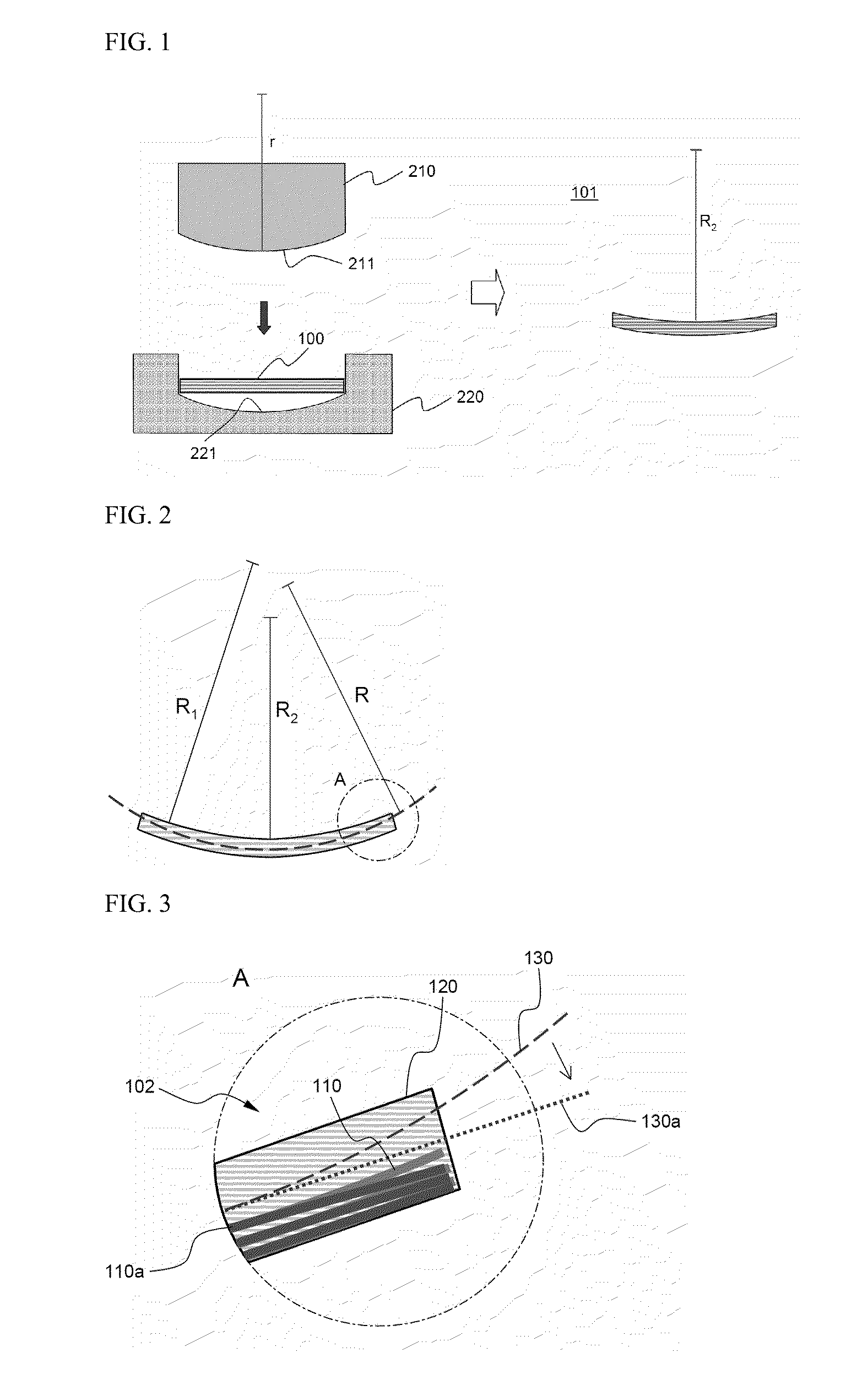
FIG. 1 is a typical view illustrating a method of manufacturing a curved battery cell according to an embodiment of the present invention.

Referring to FIG. 1, a curve forming apparatus includes an upper jig 210 with a convex part 211 having a radius of curvature r and a lower jig 220 with a concave part 221 having a radius of curvature r such that the lower jig 220 can be engaged with the upper jig 210. A battery cell 100 is configured such that an electrode assembly is provided in a cell case together with an electrolyte. The battery cell 100 is mounted in the concave part 221 of the lower jig 220 in the axial direction thereof such that the battery cell 100 can be curved in the axial direction thereof.

When the upper jig 210 is moved downward to ...


PUM

PropertyMeasurementUnit
temperatureaaaaaaaaaa
circumferenceaaaaaaaaaa
radius of curvatureaaaaaaaaaa

Abstract

The present invention relates to a battery cell which is housed in a variable state cell case in which a pole assembly having an anode / separating film / cathode laminate configuration is impregnated with an electrolytic solution. The pole assembly and the cell case are curved together in the same direction at both their ends relative to their central parts in vertical cross section in the axial direction, and they provide a battery cell having a configuration whereby they are curved in a single plane. When such a battery cell is installed in a device having a curved appearance in a single plane or is installed in a location which is curved in a single plane on the inside of a device, there are advantages in that it is efficient, can minimise waste in the space required because of the intimately fined configuration, and it allows the development of devices which have an aesthetically pleasing appearance and which have a diversity of design tailored to consumer preferences.

Description

TECHNICAL FIELDThe present invention relates to a curved battery cell and a battery pack including the same, and, more particularly, to a battery cell configured such that an electrode assembly of a cathode / separator / anode stack structure is mounted in a changeable cell case in a state in which the electrode assembly is impregnated with an electrolyte, wherein the electrode assembly and the cell case are curved in the same direction on axial vertical sections thereof in a state in which opposite ends of the electrode assembly and opposite ends of the cell case are directed in the same direction about a middle part of the electrode assembly and a middle part of the cell case.BACKGROUND ARTAs mobile devices have been increasingly developed, and the demand for such mobile devices has increased, the demand for secondary batteries has also sharply increased as an energy source for the mobile devices. Among such secondary batteries is a lithium secondary battery having high energy density...

Claims


Application Information

Patent Timeline
Patent Type & Authority Applications(United States)
IPC IPC(8): H01M2/02H01M10/36H01M50/105H01M50/119H01M50/121H01M50/124
CPCH01M2/0275H01M2/0287H01M10/0436H01M10/0459H01M10/049H01M2002/0205Y10T29/49108H01M2220/30H01M2250/30Y02B90/18Y02E60/12H01M10/04Y10T29/4911H01M2004/025Y02B90/10Y02E60/50Y02E60/10H01M50/124Y02P70/50H01M50/105H01M50/121H01M50/119H01M10/0431H01M50/202H01M50/247
Inventor GOH, EUN-YOUNGCHOI, BYUNGJINLEE, HYANG MOKJUNG, HYUN-CHUL
Owner LG ENERGY SOLUTION LTD
Why Eureka
Try Eureka