Photoacoustic imaging apparatus

a photoacoustic imaging and apparatus technology, applied in the field of bioinformation acquisition apparatus, can solve the problems of difficulty in commercial viability in cost, uneven sensitivity between the central part and the end parts of the two-dimensionally arranged electromechanical conversion elements, and waste of tim

Active Publication Date: 2011-04-28
CANON KK
View PDF5 Cites 33 Cited by
  • Summary
  • Abstract
  • Description
  • Claims
  • Application Information

AI Technical Summary

Benefits of technology

[0018]FIG. 5 is a view for describing an advantage of the invention implemented as the first embodiment.
[0019]FIG. 6 is a view illustrating the operation principle of the bioinformation acquisition apparatus according to the first embodiment (in the case of fixing the light source and moving the electromechanical conversion element group).
[0020]FIG. 7 is a view illustrating the concrete configuration of a received signal processing unit of the bioinformation acquisition apparatus according to the first embodiment.
[0021]FIG. 8 is a diagram illustrating a flow chart of the accumulation addition processing of the bioinformation acquisition apparatus according to the first embodiment.
[0022]FIG. 9 is a diagram illustrating the time transitions of the accumulation additions in the bioinformation acquisition apparatus according to the first embodiment (at the time of movements by one-element width).
[0023]FIG. 10 is a diagram illustrating the time transitions of the accumulation additions in the bioinformation acquisition apparatus according to the first embodiment (at the time of movements by two-element width).

Problems solved by technology

However, the method (1) has the problem of the difficulty of commercial viability in cost owing to the scale enlargement of the receiving system of the method.
Moreover, the method (2) has the problem of the occurrence of the unevenness of sensitivity between the central part and the end parts of the two-dimensionally arranged electromechanical conversion elements.
Moreover, the method (2) has the problem of the waste of time to locate the electromechanical conversion element group to the next positions one by one in the step and repeat system.

Method used


Image

  • Photoacoustic imaging apparatus
  • Photoacoustic imaging apparatus
  • Photoacoustic imaging apparatus

Examples


first embodiment

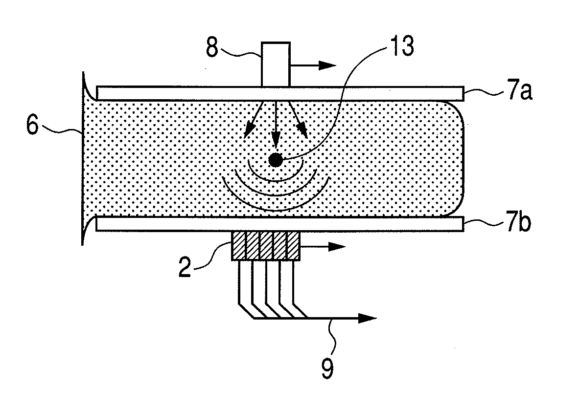
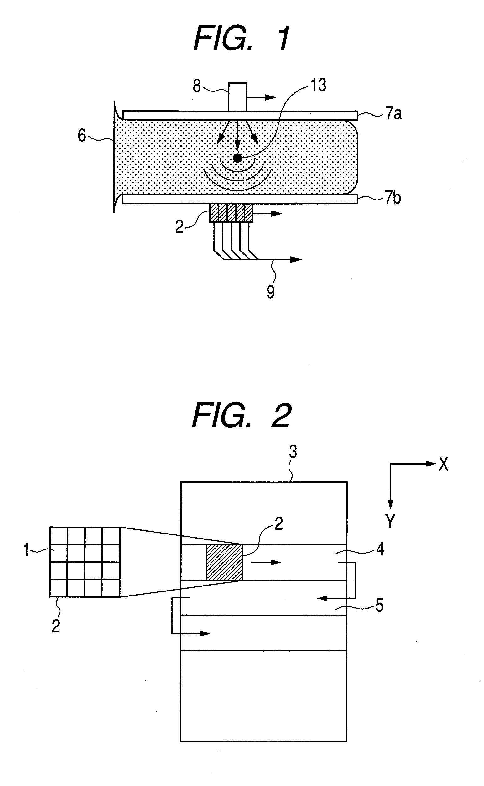
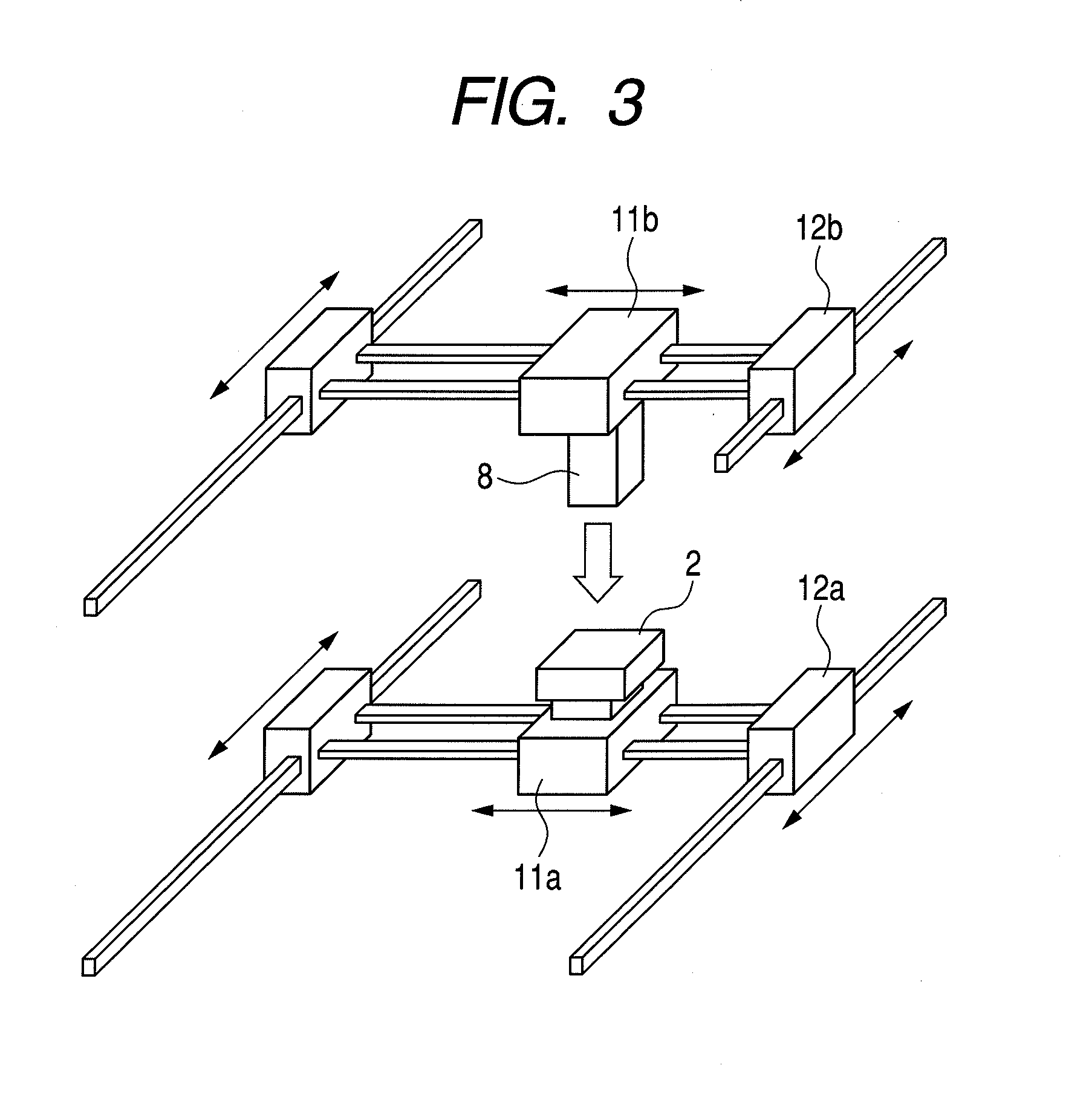
[0036]In the following, a first embodiment of the present invention will be described. A bioinformation acquisition apparatus according to the present embodiment includes a light source, as an electromagnetic wave source for generating a pulsed laser; and an electromechanical conversion element group, which includes a plurality of arranged electromechanical conversion elements, each receiving an acoustical wave, as an elastic wave generated by radiating a pulsed laser from the light source to a test object in a test body, and converting the received acoustical wave into an electric signal. Furthermore, the bioinformation acquisition apparatus includes a moving device for moving the electromechanical conversion element group into the arrangement direction of the electromechanical conversion elements, an adding device for adding the electric signals transmitted from the plurality of electromechanical conversion elements to one another, and a processing device for obtaining image infor...

second embodiment

[0068]Next, a second embodiment of the present invention will be described. The second embodiment uses an electromechanical conversion element group different from that of the first embodiment. The other respects of the second embodiments are the same as those of the first embodiment.

[0069]As illustrated in FIG. 11, an electromechanical conversion element group 51 according to the present embodiment arranges six electromechanical conversion elements 52 in their moving directions with two gaps 53, each being a two-element width, put between the electromechanical conversion elements 52. FIG. 12 illustrates temporal transitions at the time of inputting an acoustic signal every movement of a six-element width by using the electromechanical conversion element group 51. As illustrated in FIG. 12, the inputting of the acoustic signals subjected to the addition of one time can be performed in successive positions in spite of using the electromechanical conversion element group 51 with the g...

third embodiment

[0073]Next, a third embodiment of the present invention will be described. The third embodiment implements the addition processing in the direction perpendicular to the moving direction of an electromechanical conversion element group besides the addition processing in the moving direction of the electromechanical conversion element group. The other respects are the same as those of the first and second embodiments.

[0074]If acoustic signal inputting is performed by using an electromechanical conversion element group arranging M electromechanical conversion elements in the moving direction and N electromechanical conversion elements in the direction perpendicular to the moving direction, then the number of signal waveforms corresponding to the stripe length of the width of the N electromechanical conversion elements have been input into the processor 21 at the time point when a time of movement has been completed. Next, if an adjacent stripe is set so that a part of the adjacent stri...


PUM


Abstract

A bioinformation acquisition apparatus to input a signal having uniform sensitivity and a high SN ratio at a high speed is provided. It includes a moving device moving an element group into the arrangement direction of the elements, and moves the element group situated at a first position at first time point to be situated at a second position at second time point. The element group receives an elastic wave emitted from a test object at the first time point at the first position, and the elastic wave from the test object at the second time point at the second position. The electric signal of a specified position of a test body from a first element of the elastic waves received at the first time point and the electric signal of the specified position from a second element received at the second time point are added to each other.

Description

TECHNICAL FIELD[0001]The present invention relates to a bioinformation acquisition apparatus to image an elastic wave emitted from a test body.BACKGROUND ART[0002]A photoacoustic imaging method, which is a bioinformation acquisition method, is a method of detecting an acoustical wave induced in the internal portion of a living body by radiating a pulsed laser light to the living body, thereby imaging the three-dimensional structure of the internal portion of the living body. The acoustical wave is generated by the radiation of the pulsed laser light to a test object in a living body to cause the thermal expansion of the test object in the internal portion of the living body. Moreover, by changing the wavelength of the wavelength of the pulsed laser light, it is possible to visualize the distributions of specific substances, such as hemoglobin and glucose in blood, having an absorption band of the wavelength. Consequently, because a potential tumor, such as the abnormal growth of new...

Claims


Application Information

Patent Timeline
Patent Type & Authority Applications(United States)
IPC IPC(8): A61B8/08
CPCG01N29/2418G01N21/1702A61B5/0095G01S7/52085A61B5/0059A61B8/4483A61B8/08A61B5/004A61B5/708A61B5/7242
Inventor YODA, HARUO
Owner CANON KK
Why Eureka
Try Eureka