Final assembly machine and method of use

a technology of assembly machine and final assembly, which is applied in the direction of transportation and packaging, manufacturing tools, hoisting equipment, etc., can solve the problems of large plant structure and structure, large number of automated systems, and large number of vehicles, and achieve the effect of maximizing access to the vehicl

Inactive Publication Date: 2011-05-05
COMAU INC (US)
View PDF16 Cites 37 Cited by
  • Summary
  • Abstract
  • Description
  • Claims
  • Application Information

AI Technical Summary

Benefits of technology

[0014]In an exemplary build process using a final assembly machine having one or more features described above, a partially completed vehicle body is installed in the FAM, the FAM is independently p

Problems solved by technology

These facilities have utilized numerous, long and complex automated vehicle body conveying systems to transfer, for example, the heavy and large sheet metal vehicle bodies throughout the plant passing from the body framing where the sheet metal components are welded together.
Both conveying systems require substantial plant architecture and structure.
These automated transfer systems require complex transition areas where the vehicles are released from one transfer convey to another.
As such, much of the travel path of the vehicle renders it in positions where it cannot efficiently or safely be worked on by plant worke

Method used


Image

  • Final assembly machine and method of use
  • Final assembly machine and method of use
  • Final assembly machine and method of use

Examples


Embodiment Construction

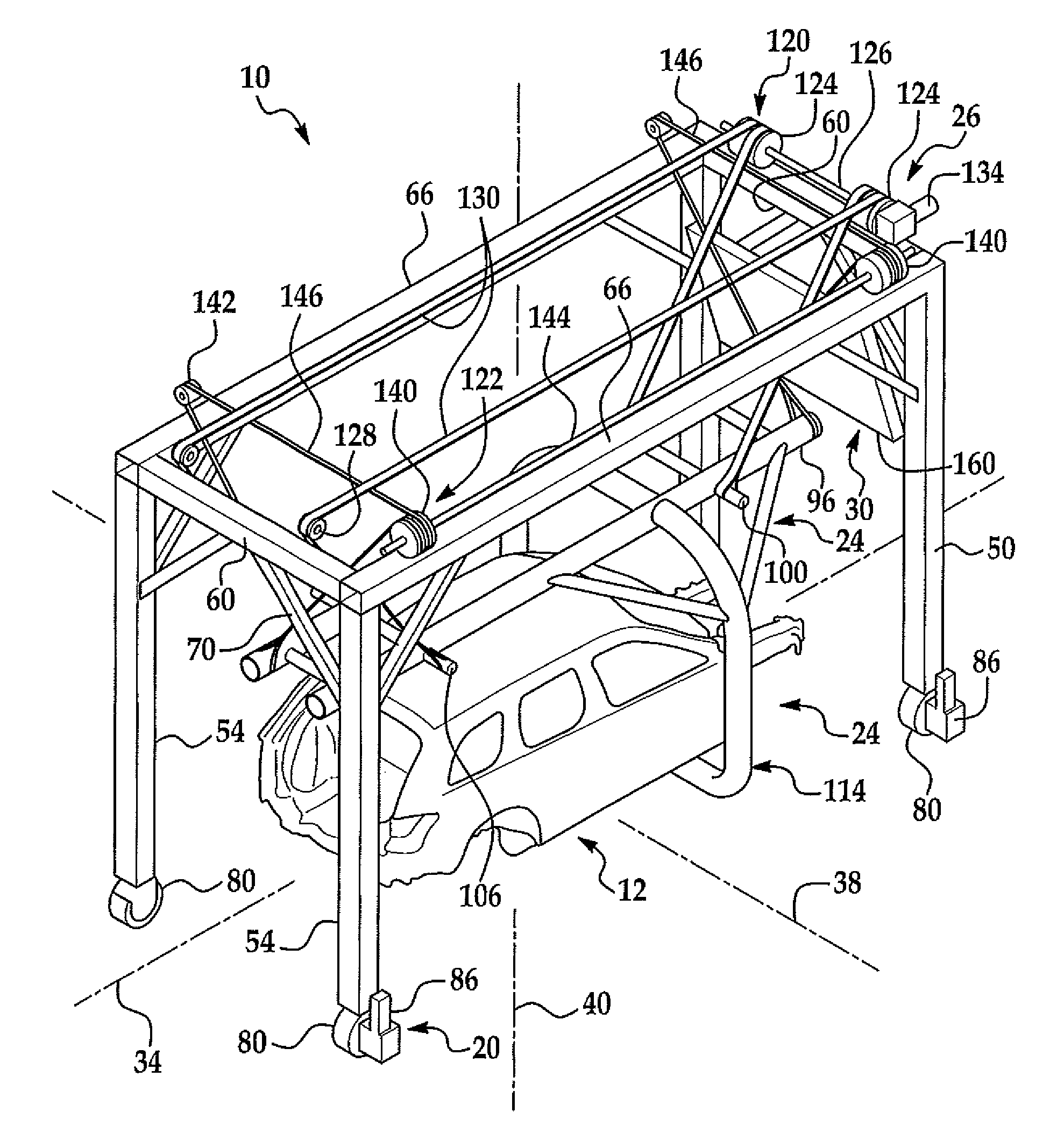
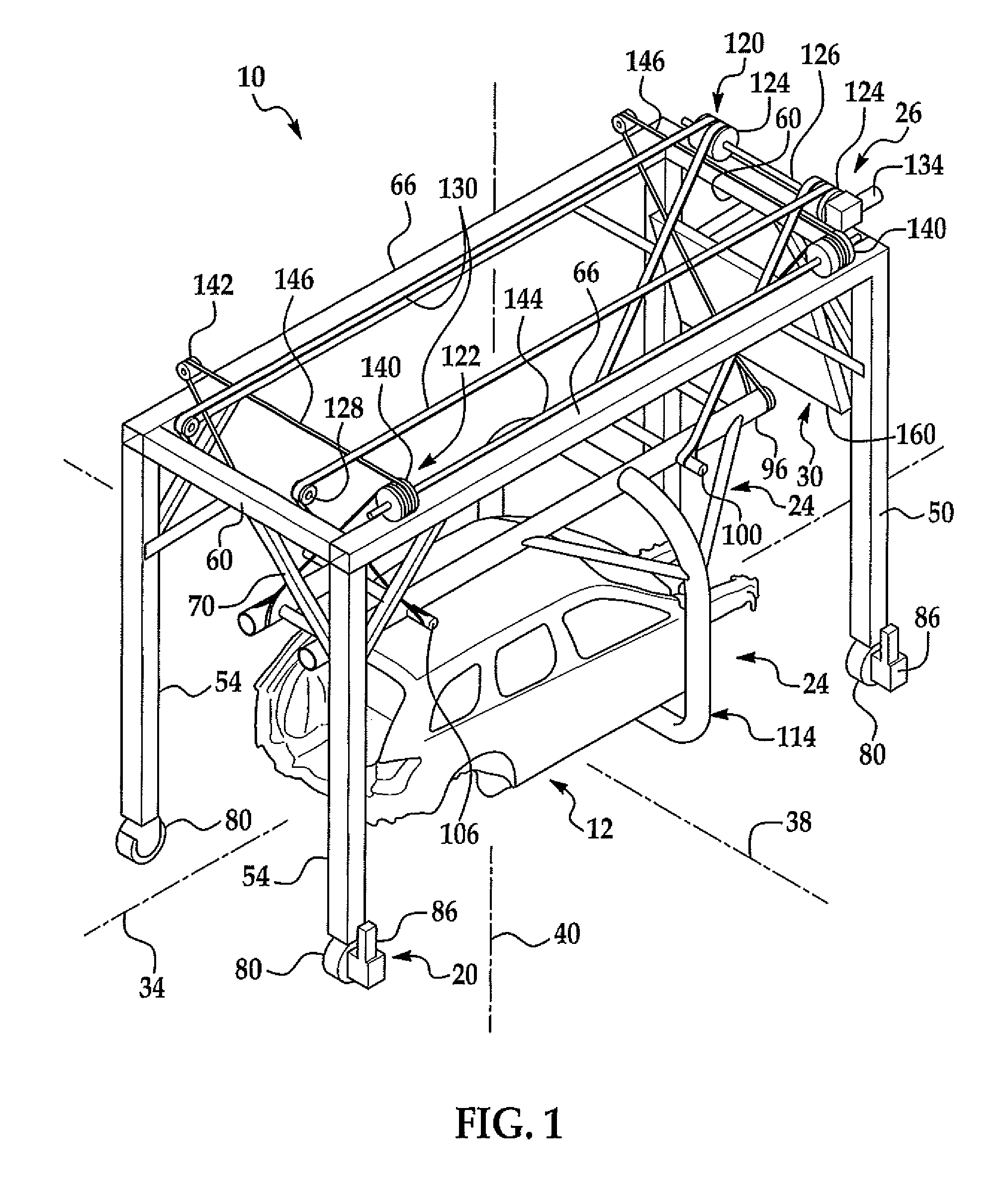
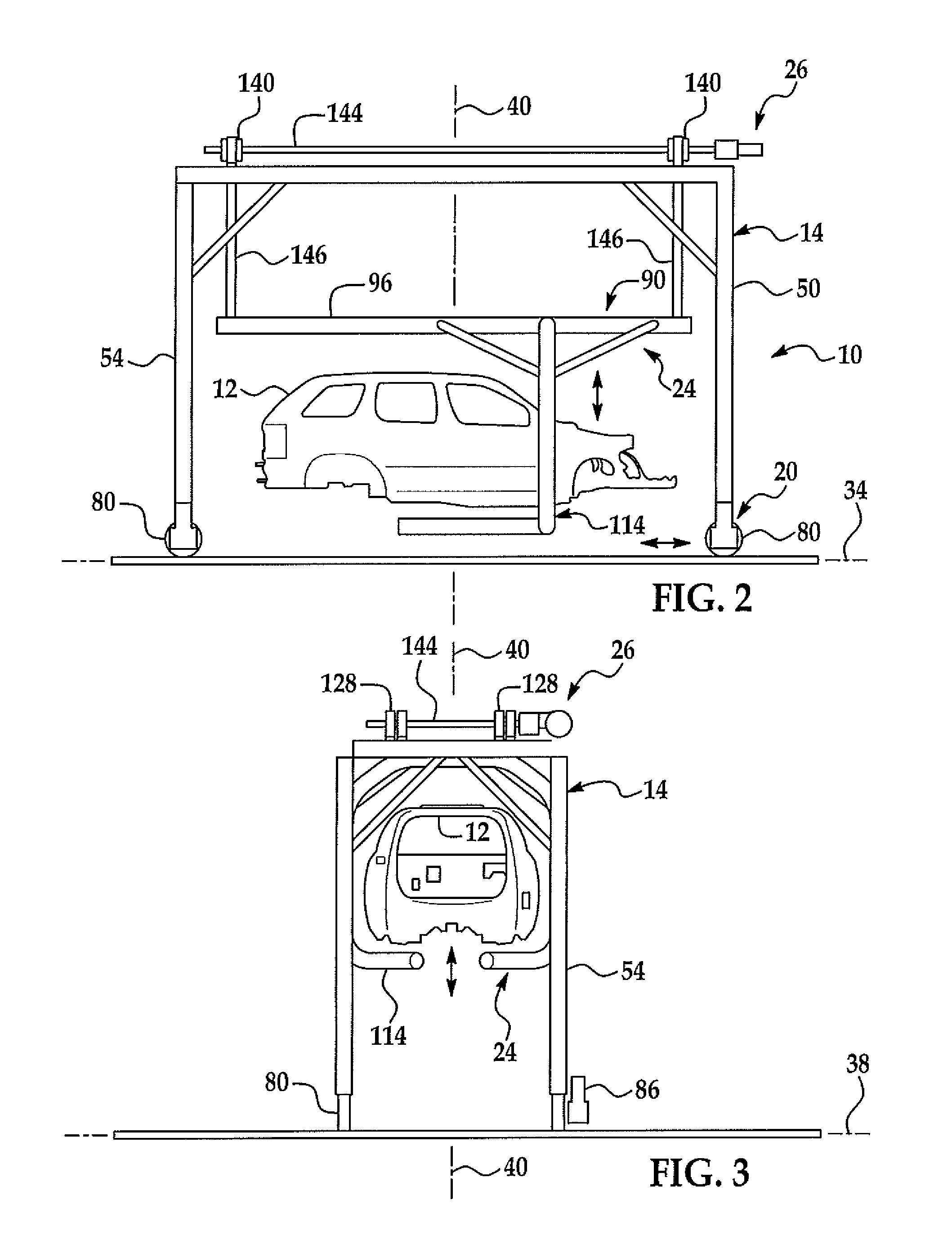
[0040]Several examples of the inventive final assembly machine (FAM) 10 and methods of use are shown in FIGS. 1-20. Referring to FIGS. 1 and 5, two alternate examples of the FAM are illustrated and further described below.

[0041]Referring to FIGS. 1-4, a first example of an FAM 10 for exemplary use in assembling a passenger vehicle body 12 is shown. In a preferred example, vehicle body 12 is a sheet metal body that has been through a production paint process.

[0042]As best seen in the example in FIG. 1, FAM 10 includes a frame 14, a powered frame drive 20, a vehicle body support cradle 24, a body raising and lowering mechanism 26 and an operator audio and video interface or display 30. In a preferred example, FAM 10 is used along a vehicle production assembly line, path of travel or axis 34. The assembly plant (not shown) and assembly line 34 further includes a lateral direction or axis 38 and a vertical direction or axis 40 as generally shown. It is understood that the FAM may be use...


PUM

PropertyMeasurementUnit
Poweraaaaaaaaaa
Areaaaaaaaaaaa
Efficiencyaaaaaaaaaa

Abstract

A final assembly machine and method of using the final assembly machine for the sequential building and assembly of a passenger vehicle. The final assembly machine includes a frame, body support and lifting device for receiving, supporting and selectively and independently raising and lowering a vehicle body along a production assembly line while additional components are installed on the vehicle. Component carts may be removably attached to the assembly machines to provide the necessary components to be installed along the assembly line eliminating storage of build components next to the assembly lines. In one example, the final assembly machines may be independently powered, and guided along an assembly line through a plurality of build stations for increased efficiency and use of assembly plant resources.

Description

CROSS-REFERENCE TO RELATED APPLICATION[0001]This application claims the priority benefit of both U.S. Provisional Patent Application Ser. Nos. 61 / 256,551 filed on Oct. 30, 2009 and Provisional Patent Application Ser. No. 61 / 358,668 filed on Jun. 25, 2010 the entire contents of both applications are incorporated herein by reference.FIELD OF THE INVENTION[0002]The present invention generally relates to the assembly of motorized vehicles.BACKGROUND OF THE INVENTION[0003]The design, development and assembly of motorized vehicles has undergone much innovation and advancement over the past decades. With the general rise of the sales of vehicles has come increasing demand for the speed of the manufacture and assembly of vehicles while increasing the quality of the build.[0004]Conventional vehicle assembly plants require a substantial amount of build out and capital investment in order to accommodate the assembly of a specific vehicle or small number of similar vehicles. These facilities ha...

Claims


Application Information

Patent Timeline
IPC IPC(8): B23P11/00B62D65/18B66D3/20B62D65/02B23P19/04
CPCB62D65/18B66C19/005Y10T29/49826Y10T29/53796B66F7/14
Inventor KILIBARDA, VELIBOR
Owner COMAU INC (US)
Why Eureka
Try Eureka