Reducing agent injection valve abnormality detection device and abnormality detection method, and internal combustion engine exhaust gas purification system

a technology of injection valve and reducing agent, which is applied in the direction of mechanical equipment, machines/engines, exhaust treatment electric control, etc., can solve the problems of reducing the quantity of pressure drop inside the supply path, deteriorating exhaust gas purification efficiency, and insufficient purification catalyst, so as to achieve efficient exhaust gas processing

Inactive Publication Date: 2011-05-05
BOSCH CORP
View PDF6 Cites 57 Cited by
  • Summary
  • Abstract
  • Description
  • Claims
  • Application Information

AI Technical Summary

Benefits of technology

[0036]Additionally, a liquid component has a much smaller compressibility than a gas component, so the influence that the pressure inside the supply path receives because of a residual quantity of a liquid component are small, and a pressure value corresponding to the difference in the suction quantity of the gas component corresponding to whether or not there is clogging of the reducing agent injection valve is precisely detected. Consequently, according to the present invention, clogging of the reducing agent injection valve is precisely detected.
[0037]Moreover, when there is used a reducing agent injection device where a circulation path in which an orifice and a one-way valve that prevents backflow of the reducing agent to the supply path side are disposed is connected to the supply path, the one-way valve becomes closed, so according to the present invention that performs clogging determination in a state where the inside of the supply path has been depressurized, a situation where an erroneous determination is made due to the state of the orifice and the one-way valve is prevented.
[0039]Further, in the reducing agent injection valve abnormality detection device of the present invention, by determining the extent of clogging of the reducing agent injection valve by comparing, with the plural threshold values, the pressure value after the elapse of the predetermined time period after the depressurization processing has been started, control for correcting the injection quantity of the reducing agent and eliminating clogging can be implemented in response to the extent of clogging.
[0040]Further, in the reducing agent injection valve abnormality detection device of the present invention, by performing determination of clogging of the reducing agent injection valve using the purge processing at the time when the internal combustion engine is stopped, determination of clogging of the reducing agent injection valve can be performed without having to deliberately execute the depressurization processing for clogging determination.
[0041]Further, in the reducing agent injection valve abnormality detection device of the present invention, by performing the depressurization processing of the inside of the supply path at the time when the internal combustion engine is started and determining the extent of clogging of the reducing agent injection valve, determination of clogging of the reducing agent injection valve is performed in a state where a liquid component is virtually nonexistent inside the supply path, so clogging of the reducing agent injection valve is more precisely detected.
[0042]Further, in the reducing agent injection valve abnormality detection device of the present invention, the reducing agent injection device uses urea selective catalytic reduction, so the reducing agent injection device can be made compact and can more efficiently perform exhaust gas processing.

Problems solved by technology

Further, sometimes, regardless of the type of reducing agent, clogging occurs in the tip portion or the inside of the reducing agent injection valve as a result of particulate matter of soot or the like or unburned fuel included in the exhaust gas entering the inside of the reducing agent injection valve and causing seizure.
Additionally, when clogging occurs in the reducing agent injection valve, it becomes difficult to inject a target quantity of the reducing agent into the inside of the exhaust pipe, the quantity of the reducing agent that should be supplied to the NOx purification catalyst becomes insufficient, and exhaust gas purification efficiency ends up deteriorating.
However, in the clogging determination methods described in JP-A-2008-180193 and JP-A-2008-202469, there is the potential for the pressure drop quantity inside the supply path to become smaller than the pressure drop quantity assumed from the injection quantity of the reducing agent, such that an erroneous determination that clogging is occurring ends up being made.
Thus, even if the quantity of a gas existing inside the supply path were a trace quantity, it would become difficult for the pressure to drop to an extent matching the injection quantity of the reducing agent because of an increase in the volume of the gas accompanying a drop in the pressure inside the supply path.
That is, as described above, in the clogging determination methods described in JP-A-2008-180193 and JP-A-2008-202469, there is the potential for an erroneous determination that clogging is occurring to end up being made even though clogging is not actually occurring.
clogging of the reducing agent injection valve,

Method used


Image

  • Reducing agent injection valve abnormality detection device and abnormality detection method, and internal combustion engine exhaust gas purification system
  • Reducing agent injection valve abnormality detection device and abnormality detection method, and internal combustion engine exhaust gas purification system
  • Reducing agent injection valve abnormality detection device and abnormality detection method, and internal combustion engine exhaust gas purification system

Examples


first embodiment

[0052]A first embodiment is a reducing agent injection valve abnormality detection device for detecting,

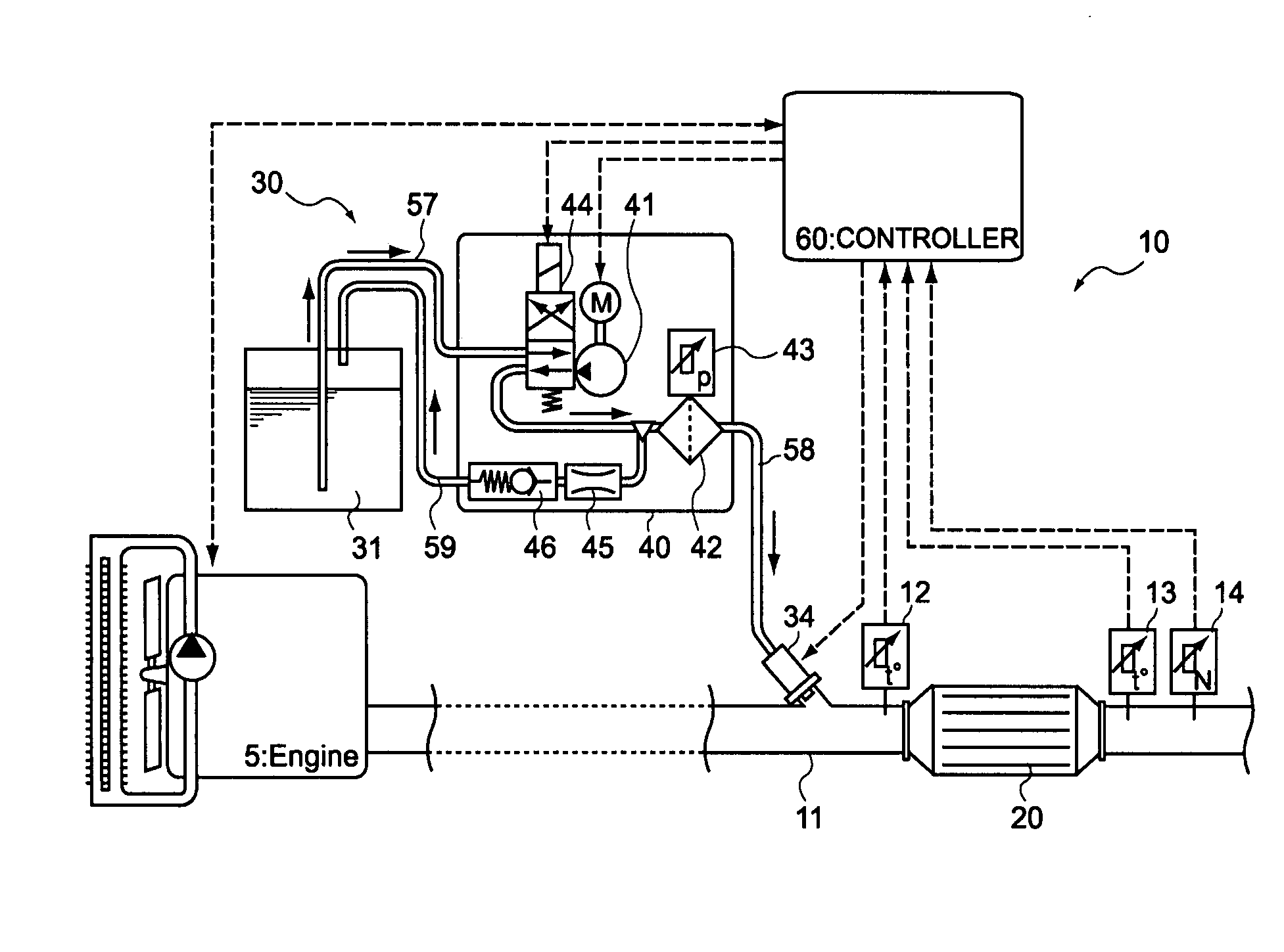
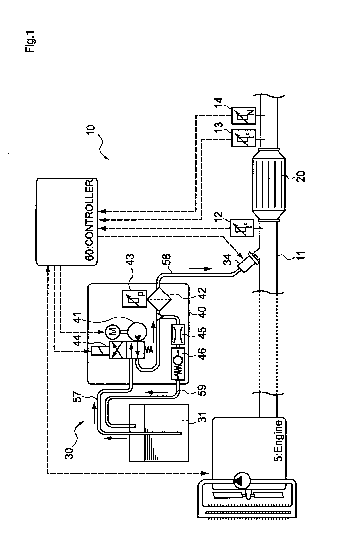
[0053]in a reducing agent injection device equipped with a storage tank that houses a reducing agent, a pump that pressure-feeds the reducing agent, a reducing agent injection valve that injects the reducing agent pressure-fed by the pump into the inside of an exhaust pipe of an internal combustion engine, a supply path that interconnects the pump and the reducing agent injection valve, and a pressure sensor that is disposed in the supply path, with the reducing agent injection device being configured such that it can suck, into the inside of the supply path, a gas inside the exhaust pipe via an injection hole in the reducing agent injection valve by subjecting the inside of the supply path to depressurization processing,

clogging of the reducing agent injection valve,

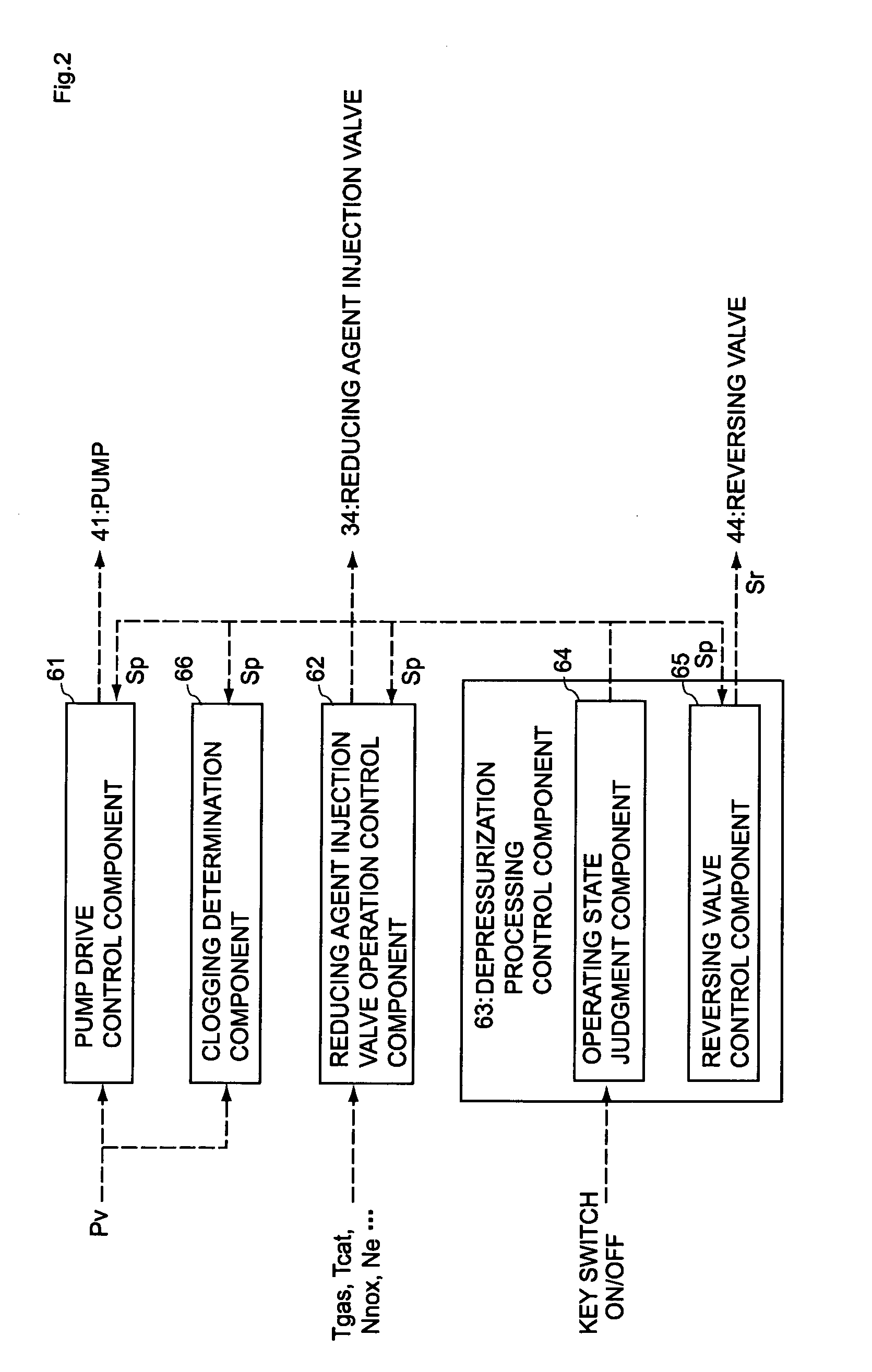
[0054]wherein the reducing agent injection valve abnormality detection device includes a clogging determination com...

second embodiment

[0141]A second embodiment of the present invention is a reducing agent injection valve abnormality detection method for detecting,

[0142]in a reducing agent injection device equipped with a storage tank that houses a reducing agent, a pump that pressure-feeds the reducing agent, a reducing agent injection valve that injects the reducing agent pressure-fed by the pump into the inside of an exhaust pipe of an internal combustion engine, a supply path that interconnects the pump and the reducing agent injection valve, and a pressure sensor that is disposed in the supply path, with the reducing agent injection device being configured such that it can suck, into the inside of the supply path, a gas inside the exhaust pipe via an injection hole in the reducing agent injection valve by subjecting the inside of the supply path to depressurization processing,

clogging of the reducing agent injection valve,

[0143]wherein the reducing agent injection valve abnormality detection method includes us...


PUM


Abstract

A reducing agent injection device is equipped with a storage tank that houses a reducing agent, a pump that pressure-feeds the reducing agent, a reducing agent injection valve that injects the reducing agent pressure-fed by the pump into the inside of an exhaust pipe of an internal combustion engine, a supply path that interconnects the pump and the reducing agent injection valve, and a pressure sensor that is disposed in the supply path. The reducing agent injection device is configured such that it can suck, into the inside of the supply path, a gas inside the exhaust pipe via an injection hole in the reducing agent injection valve by subjecting the inside of the supply path to depressurization processing. An abnormality detection device detects clogging of the reducing agent injection valve in the reducing agent injection device and includes a clogging determination component. The clogging determination component uses a pressure value detected by the pressure sensor after the start of the depressurization processing to determine whether or not clogging is occurring in the reducing agent injection valve.

Description

BACKGROUND[0001]1. Technical Field[0002]The present invention relates to an abnormality detection device and an abnormality detection method for detecting abnormality of a reducing agent injection valve that injects a reducing agent for purifying nitrogen oxides in exhaust gas into the inside of an exhaust pipe and to an internal combustion engine exhaust gas purification system.[0003]The present invention particularly relates to a reducing agent injection valve abnormality detection device and abnormality detection method for precisely detecting clogging occurring in a reducing agent injection valve and to an internal combustion engine exhaust gas purification system.[0004]2. Related Art[0005]Conventionally, nitrogen oxides (NOx) are included in exhaust gas exhausted from internal combustion engines of automobiles and the like. As one exhaust gas purification system that reduces and purifies the NOx, there is an exhaust gas purification system configured such that a NOx purificatio...

Claims


Application Information

Patent Timeline
Patent Type & Authority Applications(United States)
IPC IPC(8): F01N11/00F01N3/10
CPCF01N3/2066F01N11/00Y02T10/24F01N2610/1453Y02T10/47F01N2550/05Y02T10/12Y02T10/40
Inventor OHNO, SHIGEHIRO
Owner BOSCH CORP
Why Eureka
Try Eureka