
Key interlock device for vehicle

Inactive Publication Date: 2011-05-05
HYUNDAI MOTOR CO LTD +1
View PDF19 Cites 7 Cited by
  • Summary
  • Abstract
  • Description
  • Claims
  • Application Information

AI Technical Summary

Benefits of technology

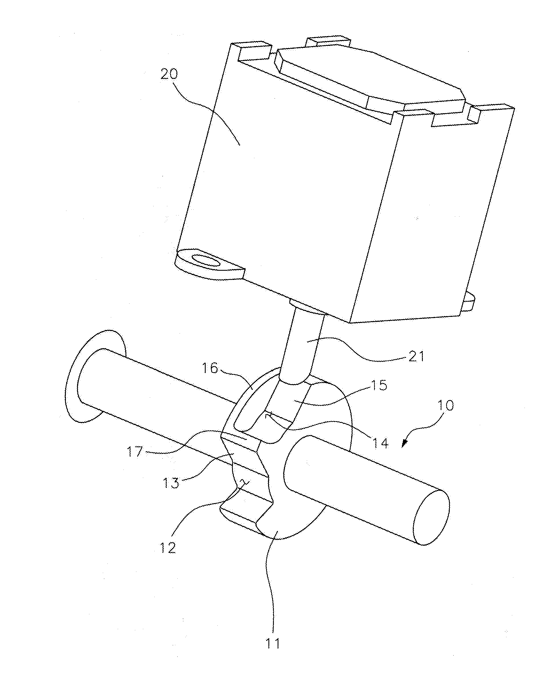
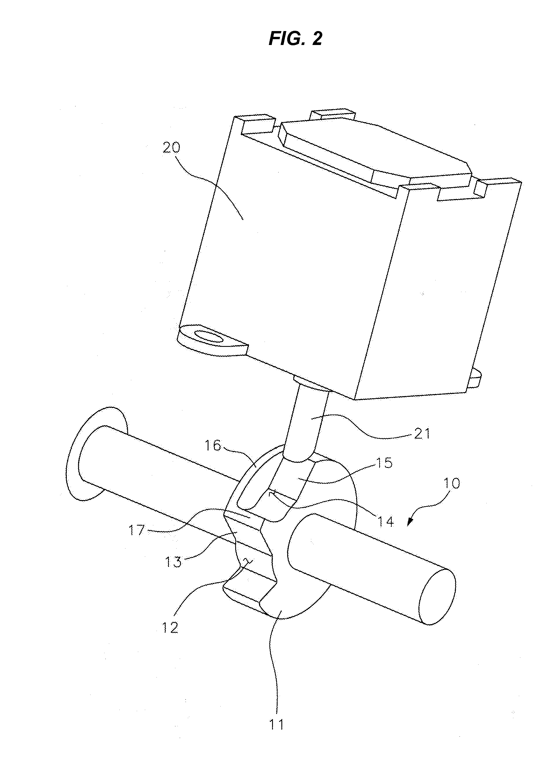
[0011]Various aspects of the present invention are directed to provide a key interlock device that ensures stability by reducing factors causing load in an ATM, and prevents overheat by changing a push type solenoid of the related art into a pull type solenoid (in which a lock bar protruding from the solenoid is moved back inside the solenoid by an electric signal).
[0018]The lock bar may be coupled to the second curved portion in a predetermined time period after the key turns to the START position to prevent the key from turning from the ON position to the ACC position.
[0019]According to the present invention having the above configuration, since the camshaft cannot physically rotate when the key is at the ON position and can rotates only when power is supplied to the solenoid, it is possible to reduce electric load.
[0020]Further, since the inclined surface is formed at the lower end of the lock bar and can slide in one direction in the first curved portion and the second curved portion, it is possible to minimize the operational time of the solenoid. Therefore, it is possible to reduce noise and electric load by the operation of the solenoid.
[0022]In addition, since a pull type solenoid is used and power supplied to the solenoid is cut after predetermined time has passed, it is possible to prevent overheat and pull out the key even in an emergency, such as when the power supplied to the solenoid is cut.

Problems solved by technology

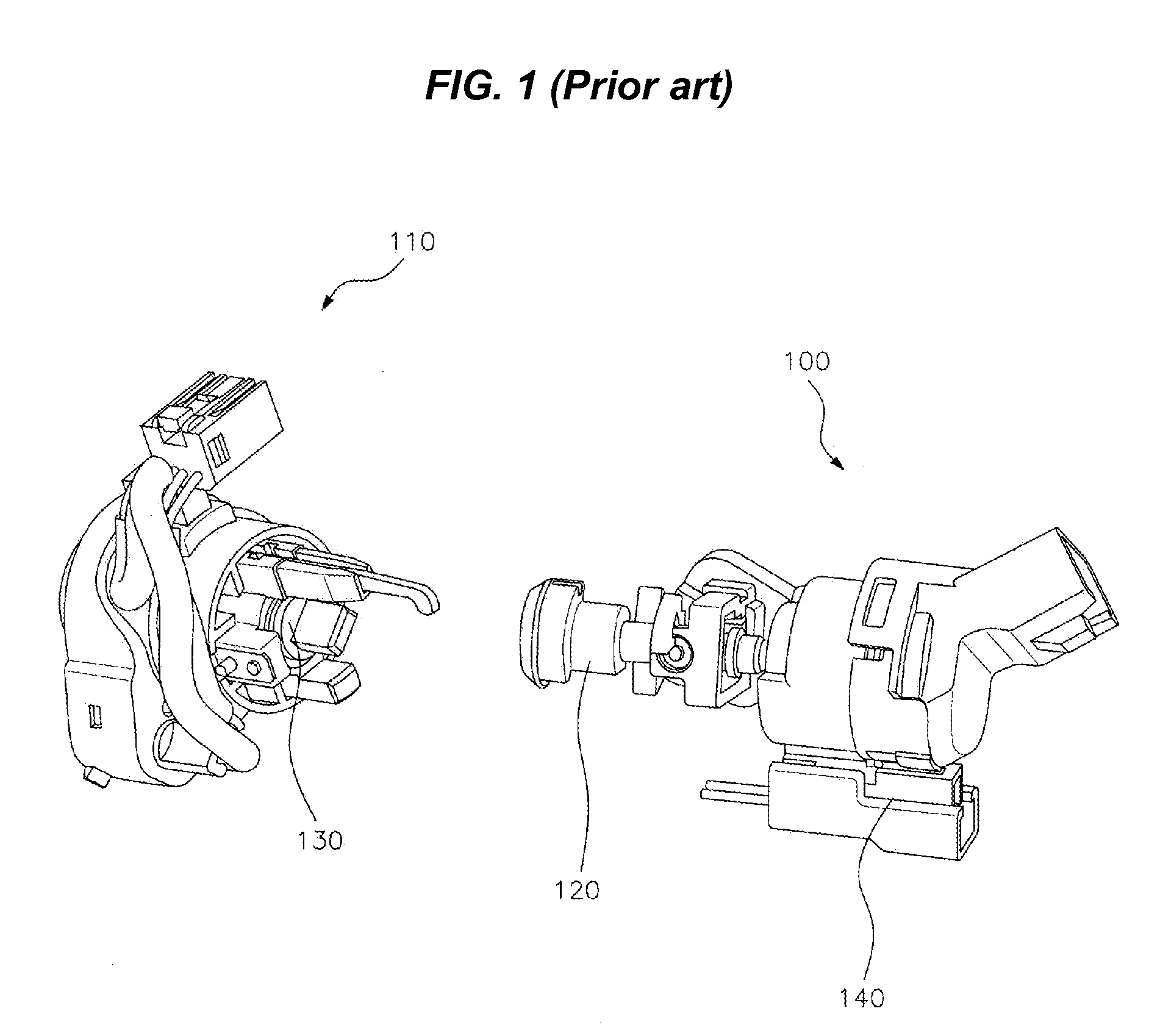
However, there was a problem that it requires an additional electrical connection, such that the electric load increases in the device.
Further, there was a problem that since a solenoid controlling the turn of a key set operates when the shift lever is moved from the P (parking) position to the R (rearward) position, this configuration makes a noise when the shift lever is moved.
Further, there was a problem that due to continuously applying the battery's voltage, the solenoid may become overheated, for characteristics of the push type solenoid (a lock bar inserted at a predetermined depth in the solenoid is protruded by an electric signal).

Method used


Image

  • Key interlock device for vehicle
  • Key interlock device for vehicle
  • Key interlock device for vehicle

Examples


Embodiment Construction

[0030]Reference will now be made in detail to various embodiments of the present invention(s), examples of which are illustrated in the accompanying drawings and described below. While the invention(s) will be described in conjunction with exemplary embodiments, it will be understood that present description is not intended to limit the invention(s) to those exemplary embodiments. On the contrary, the invention(s) is / are intended to cover not only the exemplary embodiments, but also various alternatives, modifications, equivalents and other embodiments, which may be included within the spirit and scope of the invention as defined by the appended claims.

[0031]A key interlock device for a vehicle according to exemplary embodiments of the present invention is described hereafter in more detail with the accompanying drawings.

[0032]Referring to FIG. 2, a key interlock device, in an exemplary embodiment of the present invention, has a structure in which a circular locking plate 11 increas...


PUM


Abstract

A key interlock device for a vehicle may include camshaft including a locking plate, wherein the locking plate has a first curved portion and a second curved portion to form an inter-wall therebetween, a solenoid including a lock bar disposed above the locking plate, and a controller that detects whether the shift lever is at the PARK position and the position of the key and controls the lock bar to be coupled to or decoupled from the locking plate in accordance with the detected result, wherein the lock bar is coupled to the first curved portion while the key is at the LOCK position, and is disposed above the second curved portion when the key is at the ON position, and wherein the lock bar prevents the key from turning from the ON position to the ACC position while the lock bar is coupled to the second curved portion.

Description

CROSS-REFERENCE TO RELATED APPLICATION[0001]The present application claims priority to Korean Patent Application No. 10-2000-0103905, filed on Oct. 30, 2009, the entire contents of which is incorporated herein for all purposes by this reference.BACKGROUND OF THE INVENTION[0002]1. Field of the Invention[0003]The present invention relates to a key interlock device for a vehicle which allows a key to be pulled out only when the shift lever of vehicles equipped with an automatic transmission is in the ‘park position’ P, in more detail, a key interlock device that physically prevents a camshaft from rotating.[0004]2. Description of Related Art[0005]Key interlock devices of vehicles with an automatic transmission prevent vehicles from unexpectedly starting and parked vehicles from moving, by allowing the vehicle to start only when the shift lever is at the P position and allowing the key from being pulled out only when the shift lever is at the P position and the key is at the LOCK positi...

Claims


Application Information

Patent Timeline
IPC IPC(8): B60R25/00E05B65/12E05B47/00B60R25/0215B60R25/04B60R25/06E05B81/08E05B83/00
CPCB60R25/2063B60R25/00Y10T70/565B60R25/0215E05B79/00E05B81/08
Inventor CHO, YOUNG-BUMCHUNG, JIN-SANG
Owner HYUNDAI MOTOR CO LTD
Features
  • Generate Ideas
  • Intellectual Property
  • Life Sciences
  • Materials
  • Tech Scout
  • Unparalleled Data Quality
  • Higher Quality Content
  • 60% Fewer Hallucinations
Learn More