Vortex incinerator

a technology of incinerators and incineration chambers, which is applied in the direction of incinerator equipment, combustion types, lighting and heating equipment, etc., can solve the problems of insufficient cleaning of flue gas, high cost and bulky construction of cleaning equipment, and inability of prior incinerator designs to achieve good combustion of waste materials. , to achieve the effect of reducing air and water pollution

Inactive Publication Date: 2011-05-05
HASSELBRING ROBERT JOEL +1
View PDF2 Cites 37 Cited by
  • Summary
  • Abstract
  • Description
  • Claims
  • Application Information

AI Technical Summary

Benefits of technology

[0008]It is therefore a primary object of the invention to provide a novel and improved incinerator capable of effecting substantially complete combustion of waste material and wherein essentially solid-free flue gases are discharged to the atmosphere to minimize air and water pollution.

Problems solved by technology

Prior incinerator designs in general have been incapable of effecting good combustion of waste material such that the products of the resulting incomplete combustion consist of a large quantity of noxious gases and ash which are discharged to the surrounding atmosphere in the form of dense acrid smoke.
Such flue gas cleaning apparatus is usually of costly and bulky construction and in some cases has not operated to clean the flue gases sufficiently to comply with the regulatory codes.
This type of flue gas cleaning apparatus is expensive and complex and contributes not only to the high cost and massive structure of prior art incinerators, but also to water pollution.
Further, the very high temperatures within the chambers necessary to effect good combustion result in very hot flue gases which may result in inefficient operation of the flue gas cleaning apparatus and resulting undesirable pollution of the surrounding atmosphere.
The provision of flue gas cleaning apparatus thus imposes a limitation upon the temperature within the combustion chambers which contributes to the poor combustion realized by certain prior art designs.
Such conveying apparatus is also very costly and in addition, occupies considerable space which further contributes to the high cost and massive structure of prior art incinerators.

Method used


Image

  • Vortex incinerator
  • Vortex incinerator
  • Vortex incinerator

Examples


Embodiment Construction

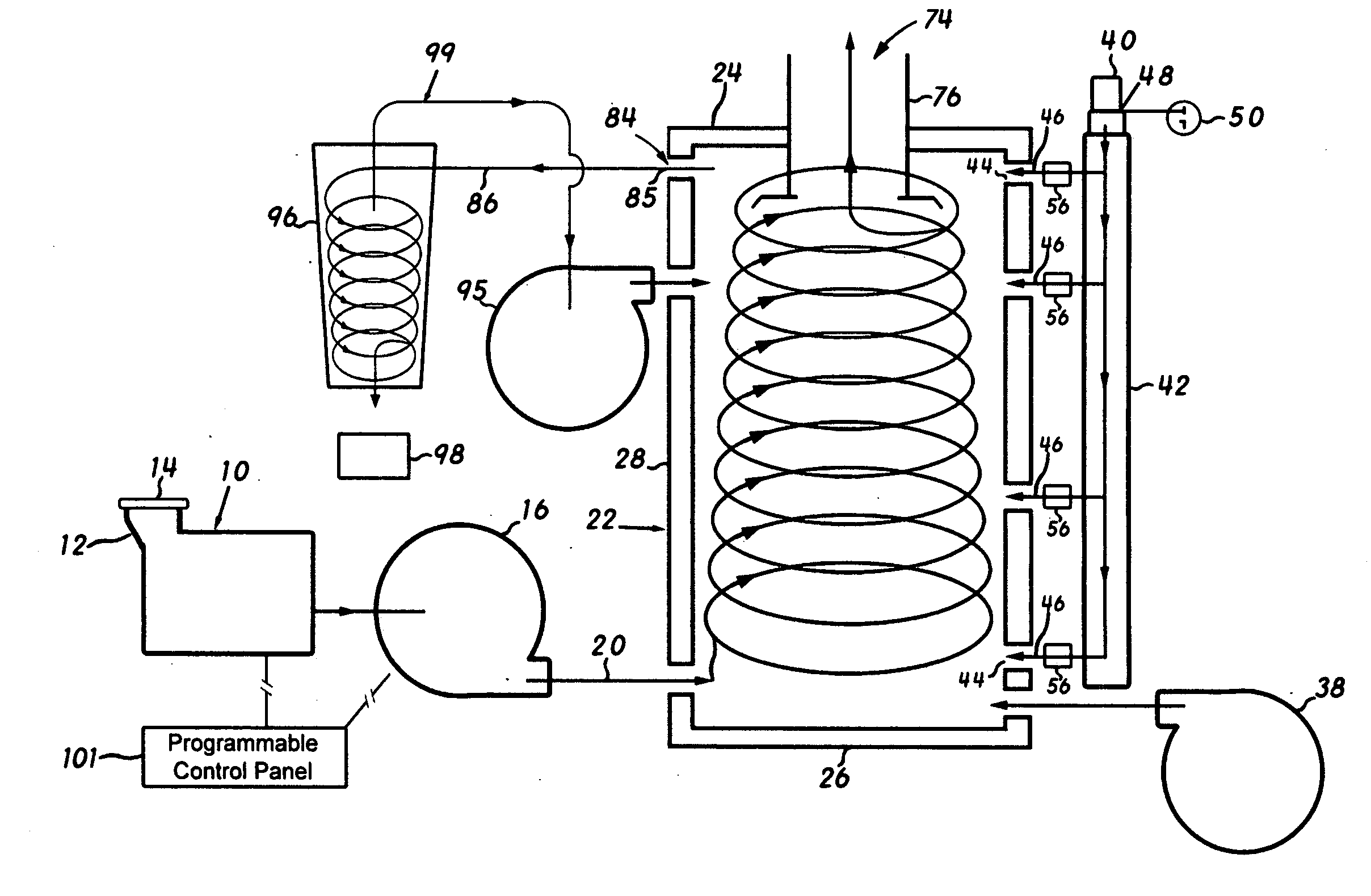
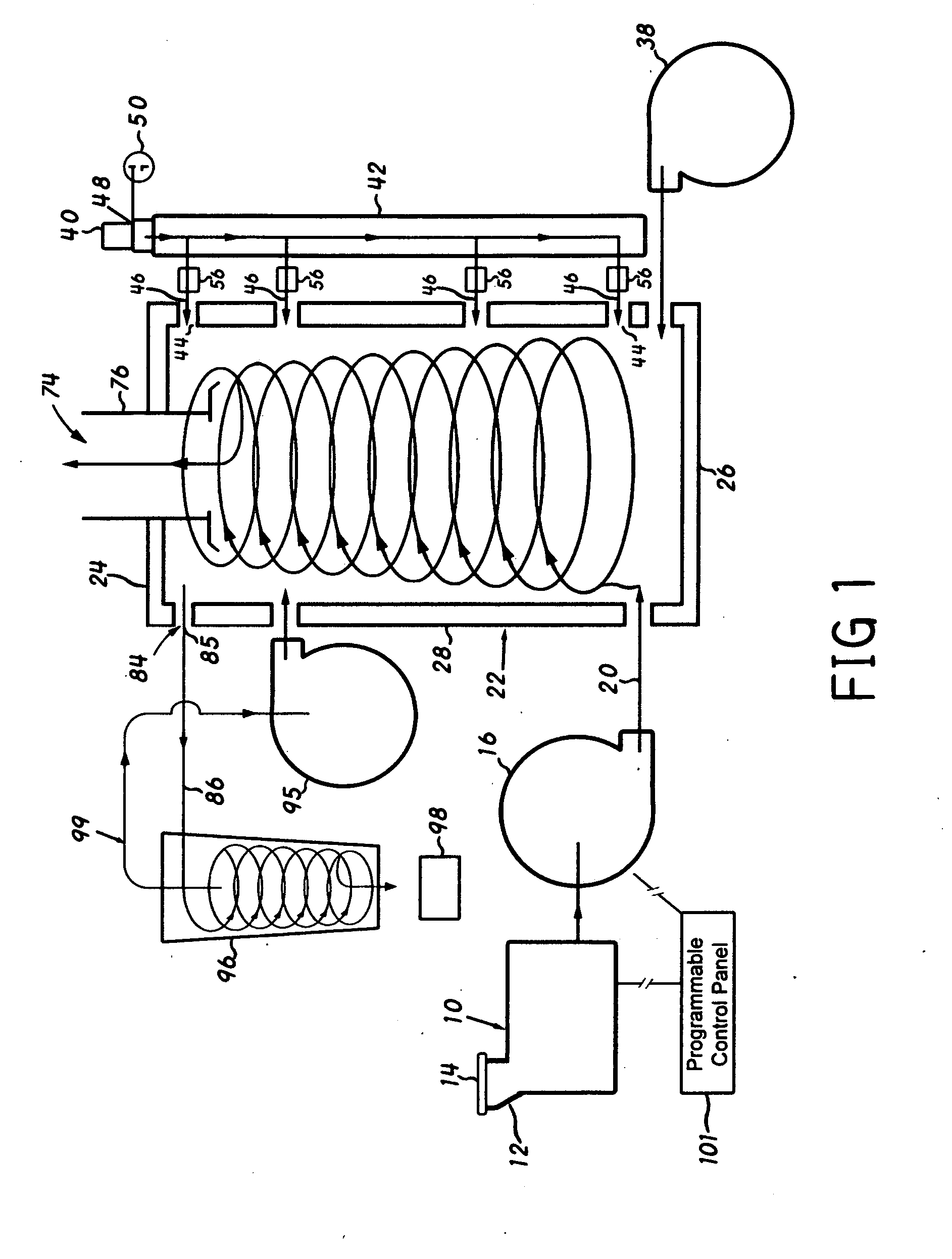
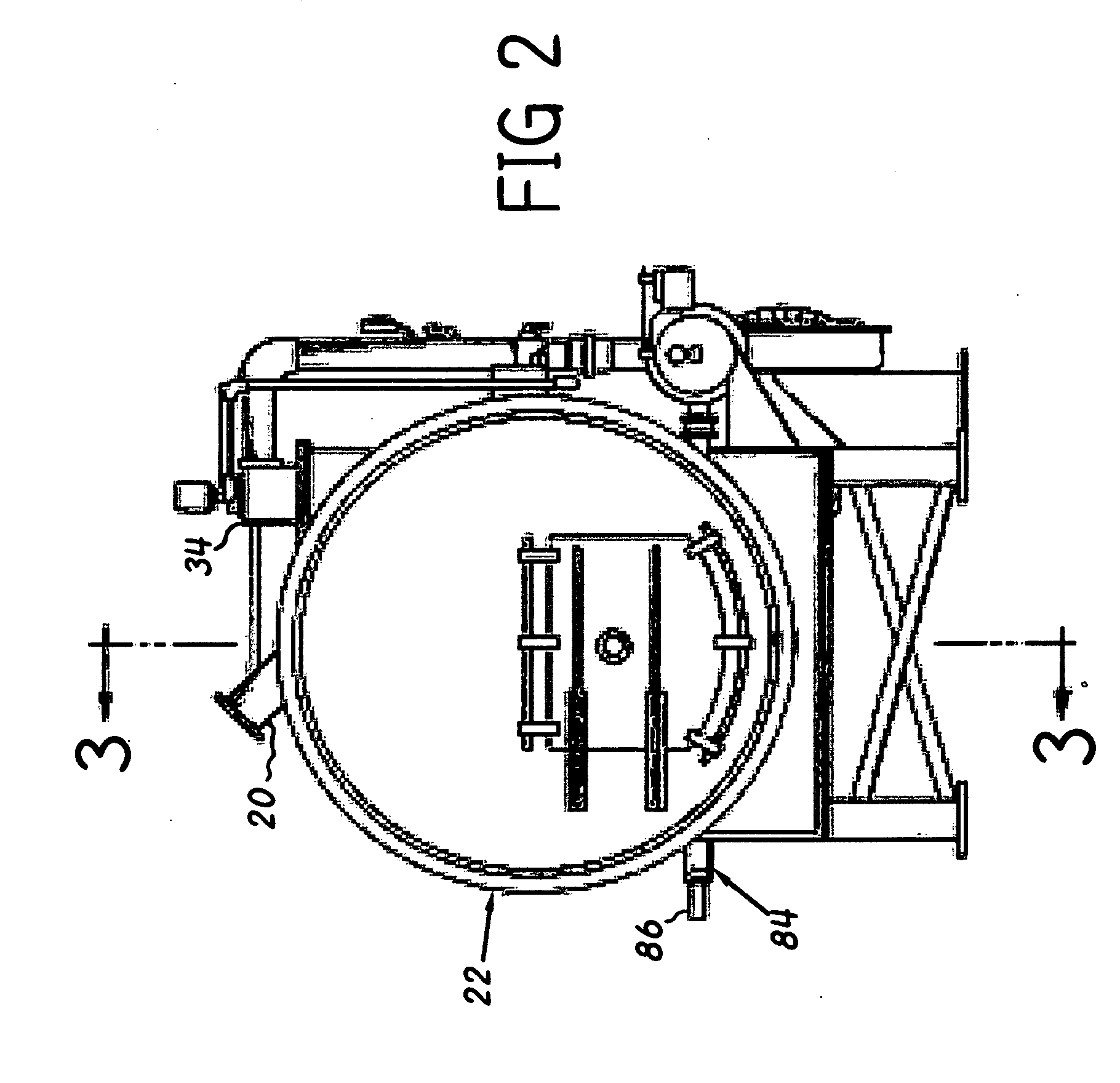
[0025]Referring now to the drawing there is illustrated in FIGS. 1-4 an incinerator embodying the invention and comprising in general a size reduction unit for chopping up the waste material, means for introducing the waste material and primary air into a combustion chamber for establishing a vortical movement of the waste material, means for igniting the waste material during its vortical movement, means for introducing secondary air into the chamber, discharge means for discharging gaseous products of combustion, and non-combustible material from the combustion chamber, and a separator for separating the gaseous and solid material discharged by the discharge means. The incinerator of the present invention is particularly suited for disposing of solid industrial and municipal waste materials, including but not limited to standard waste, such as for example, paper, peanut hulls, cardboard cartons, wood scrap, garbage, foliage, woody biomass, bottles, cans, plastic items and more. Ho...


PUM


Abstract

An incinerator for burning waste material includes a horizontally extended combustion chamber through which a mixture of waste material and air is introduced under pressure tangentially for establishing a vortical movement of the waste material toward one of the end walls. The waste material is ignited during its vortical movement. A second discharge port extends for discharging from the chamber non-combustible material entrained in the outer region of the vortex. The discharged material is conveyed through a conduit to a separator which separates the discharged gases and solid material. A baffle is mounted on the flue adjacent its open end for deflecting outwardly toward the side wall solid material which moves from adjacent the one end wall toward the open end of the flue. Additionally, control means are provided for the use of specialized sensors to monitor the temperature, air flow and volume of the chamber.

Description

CROSS-REFERENCE TO RELATED APPLICATIONS[0001]Certain features disclosed in this application are disclosed and claimed in U.S. Pat. No. 3,577,940 issued on May 11, 1971 to Robert J. Hasselbring and Robert L. Shields, and U.S. Pat. No. 3,727,563 issued on Apr. 17, 1973 to Robert J. Hasselbring and Robert L. Shields, and U.S. Pat. No. 3,568,017 issued on Apr. 25, 1972 to Norman R. Dibelius and William L. Zabriskie.BACKGROUND OF THE INVENTION[0002]1. Field of the Invention[0003]This invention relates to incinerators and has particular relation to industrial and municipal-type incinerators for burning waste material.[0004]2. Description of the Prior Art[0005]Conventional industrial and municipal type incinerators ordinarily include one or more combustion chambers having drying grates with a flue for discharging to atmosphere the gaseous products of combustion of waste material in the chambers. Depending upon the efficiency of a particular incinerator design varying amounts of noxious gas...

Claims


Application Information

Patent Timeline
Patent Type & Authority Applications(United States)
IPC IPC(8): F23G5/32
CPCF23G5/32F23G5/50F23J15/027F23N3/002F23L9/02F23L9/04F23M9/06F23L1/00F23G5/24
Inventor HASSELBRING, ROBERT JOELVANNATTA, RALPH WALLACE
Owner HASSELBRING ROBERT JOEL
Why Eureka
Try Eureka