Granular metallic iron

Inactive Publication Date: 2004-04-22
IDREX INT BV ROTTERDAM ZURICH BRANCH
View PDF19 Cites 20 Cited by
  • Summary
  • Abstract
  • Description
  • Claims
  • Application Information

AI Technical Summary

Benefits of technology

0097] As is apparent from these experiments, when an adequate amount of a CaO source is intentionally added to the material compacts to increase the basicity of the slag component to approximately 0.6 or more, the produced slag captures a significantly larger amount of sulfur, and the amount of the sulfur captured in the metallic iron nuggets can thus be significantly reduced. As a result, metallic iron nuggets that satisfy the level of the sulfur content required in the present invention, i.e., metallic iron nuggets having a sulfur content of 0.08% or less, can be easily manufactured. Furthermore, as described above with reference to FIG. 10, the amount of sulfur discharged outside the furnace as SO.sub.X or the like during a series of metallic iron nuggets manufacturing steps can be drastically reduced. Thus, air pollution due to effluent gas can be minimized. Moreover, load of desulfurizing the effluent gas can be significantly reduced if desulfurization treatment of the effluent gas is performed.
0098] When the CaO source is added to reduce the S content, as described above, bleeding of low-melting point slag which leads to dissolution of the hearth refractories may occur during the reducing-melt period due to a decrease in the melting point of the by-product slag depending on the amount of the CaO source added. In implementing the above-described process, a two-stage heating method including a solid reduction period and a carburization, melting, and cohesion period is preferably performed. During the solid-reduction period, the temperature is preferably adjusted to 1,200 to 1,400.degree. C., and during the carburization, melting, and cohesion period, the te

Problems solved by technology

In particular, in a method for making sponge metallic iron, the Fe purity is drastically low because the separation of the slag component that became mixed in the metallic iron is difficult.
Moreover, nearly all of the metallic iron obtained by a known direct iron-making process is sponge-shaped, and thus the handling thereof as an iron source is difficult since such metallic iron is fragile.
In order to actually use such metallic iron as a material for making iron, steel, or alloy steel, a process such as a secondary process to make briquettes therefrom is required, and the expenses for additional equipment therefor are considerable.
In the known processes, including these

Method used


Image

  • Granular metallic iron
  • Granular metallic iron
  • Granular metallic iron

Examples


example 1

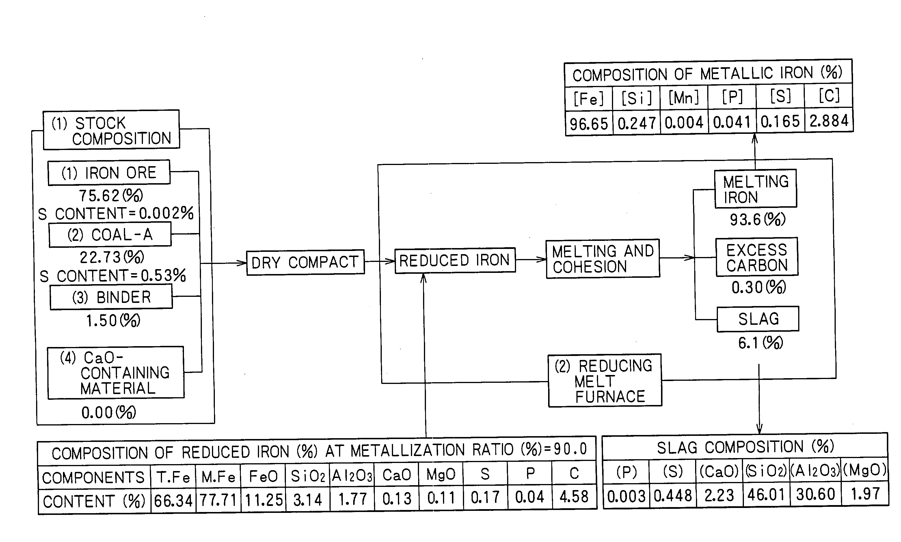
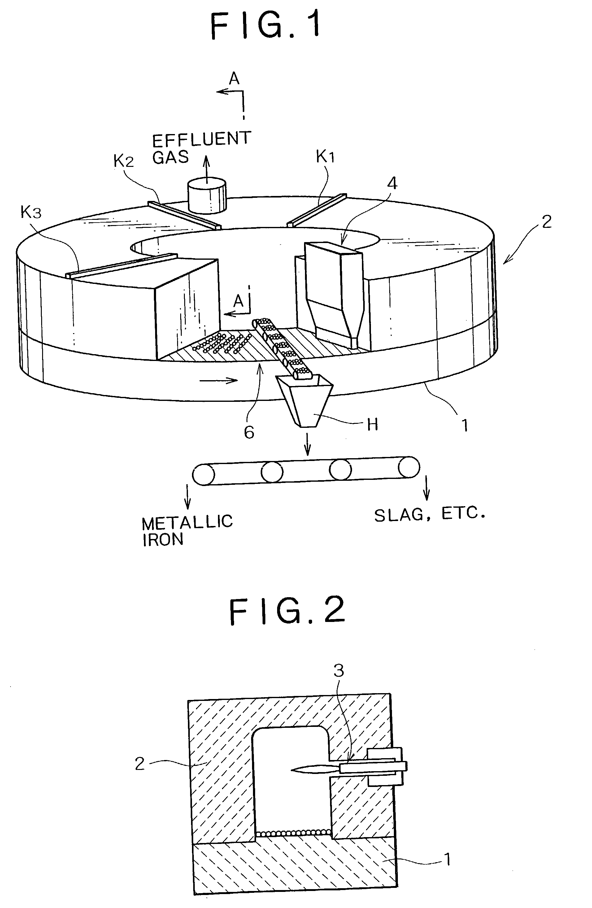
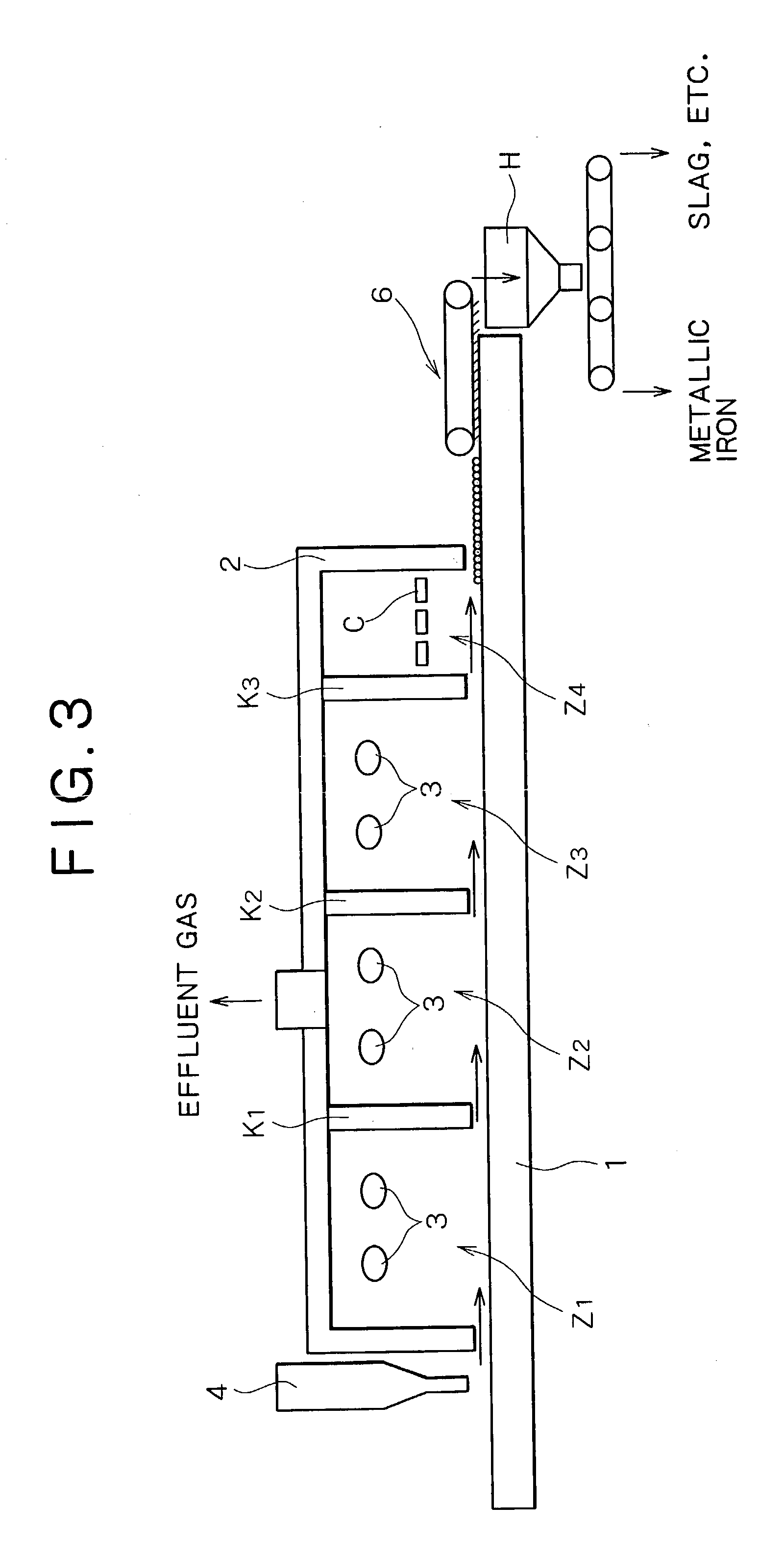
[0102] Material compacts having a diameter of approximately 19 mm were made by uniformly mixing hematite ore, i.e., an iron source, coal, and a small amount of a binder (bentonite). Metallic iron was made using these material compacts. The material compacts were fed inside a reducing-melt furnace of a rotary hearth type shown in FIGS. 1 to 3, and solid reduction was performed at an atmosphere temperature of approximately 1,350.degree. C. until a metallization ratio of approximately 90% was reached. Subsequently, the resulting material compacts were transferred to a carburization, melting, and cohesion zone at an atmosphere temperature of 1,440.degree. C. so as to perform carburization, melting, and cohesion, and to separate by-product slag to make slag-free metallic iron nuggets.

[0103] In this process, coal powder, i.e., an atmosphere adjustor, having a diameter of 2 mm or less was bedded on a hearth to a thickness of approximately 5 mm before the material compacts were fed to the f...

example 2

[0105] Material compacts having a diameter of approximately 19 mm were made by uniformly mixing magnetite ore, i.e., an iron source, coal, a small amount of a binder (bentonite), and 5% of CaCO.sub.3 as a slag basicity adjustor and forming the resulting mixture into compacts.

[0106] The material compacts were fed on a bed of coal powder (average diameter: approximately 3 mm) having a thickness of approximately 3 mm, the bed of coal powder being formed on a hearth. The coal powder was used as an atmosphere adjustor. The solid reduction was performed as in Example 1 while maintaining the atmosphere temperature at approximately 1,350.degree. C. until the metallization ratio reached nearly 100%. Subsequently, the resulting material compacts were transferred to a melting zone maintained at 1,425.degree. C. so as to perform carburization, melting, cohesion, and separation of by-product slag so as to make slag-free metallic iron. The material composition, the composition of the reduced iron...

example 3

[0112] An experiment was conducted under the same conditions as those in Example 1 and an actual furnace. In this experiment, the diameter of the material compacts (pellets) was varied within the range of 3 to 35 mm to examine the effect of the size of the material compacts on the average diameter and the average mass of the resulting metallic iron nuggets. The results are shown in FIG. 16.

[0113] As is apparent from this graph, metallic iron nuggets having a diameter in the range of 5 to 20 mm, i.e., the type of metallic iron nuggets exhibiting superior handling quality as the end-product metallic iron, could be effectively manufactured from material compacts (dry pellets) having a diameter of approximately 10 to 35 mm.

[0114] Industrial Applicability

[0115] The present invention having the above-described configuration provides metallic iron nuggets having a high Fe purity, an adequate C content, and a suitable size for handling ease. The metallic iron nuggets further has low S, Si, ...


PUM

PropertyMeasurementUnit
Fractionaaaaaaaaaa
Fractionaaaaaaaaaa
Fractionaaaaaaaaaa

Abstract

Metallic iron nuggets made by reducing-melt of a material containing a carbonaceous reductant and a metal-oxide-containing material, the metallic iron nuggets comprising at least 94% by mass, hereinafter denoted as "%", of Fe and 1.0 to 4.5% of C, and having a diameter of 1 to 30 mm are disclosed.

Description

[0001] The present invention relates to metallic iron nuggets made by reducing-melt of a material containing iron oxide, such as iron ore, and a carbonaceous reductant, such as coke, the metallic iron nuggets having a high Fe purity, specified C, S, Si, and Mn contents, and a specified diameter.[0002] A direct iron-making process for making reduced iron by direct reduction of an iron oxide source such as iron ore using a carbonaceous substance or a reducing gas has long been known. Extensive research has been conducted as to the specifics of the reducing process and continuous reduction equipment.[0003] For example, Japanese Unexamined Patent Application Publication No. 11-337264 discloses a rotary hearth that allows efficient continuous production of reduced iron, in which, during reduction by heating of green pellets prepared by solidifying a mixture of an iron oxide source such as steelmaking dust or fine ore and a carbonaceous substance using a binder, explosions which occur whe...

Claims


Application Information

Patent Timeline
IPC IPC(8): C21B13/00C21B13/10C22C37/10C22C38/02C22C38/04
CPCB22F9/06B22F2998/10F27B9/39F27B9/16C22C38/02C22C37/10C22C37/00B22F2999/00C21B13/0006C21B13/0046C21B13/008C21B13/105B22F9/20B22F2201/30C21B2100/42Y02P10/134C22C35/00
Inventor ITO, SHUZOTANIGAKI, YASUHIROKOBAYASHI, ISAOTSUGE, OSAMUHONDA, KEISUKETOKUDA, KOJIKIKUCHI, SHOICHI
Owner IDREX INT BV ROTTERDAM ZURICH BRANCH
Why Eureka
Try Eureka