Supercharge Your Innovation With Domain-Expert AI Agents!

Central vacuum inlet valve assembly

a technology of inlet valve and vacuum, which is applied in the direction of pipes/joints/fittings, thin material processing, pipes, etc., can solve the problems of loss of suction, inability to use the whole system, and inability to manufacture in large quantities, and achieve the effect of being cheap to mak

Active Publication Date: 2011-05-05
CANPLAS INDS
View PDF17 Cites 11 Cited by
  • Summary
  • Abstract
  • Description
  • Claims
  • Application Information

AI Technical Summary

Benefits of technology

[0009]The present invention provides a vacuum inlet valve assembly in which the basic components can be configured in various ways to suit most installation requirements. The components include a cover plate, which combines a door hinged to a face plate, a valve body, which can be used with just the cover plate in a retrofit installation or combined with a mounting flange in new construction. Each component is preferably a plastic molded part that is relatively inexpensive to make in large quantities. The valve body is designed with interlocking, inter-engaging, interference fit, or press catch connection elements to permit the mounting flange to be snap or press fit onto the valve body without requiri

Problems solved by technology

However, problems exist with the prior art inlet valve assembly designs.
One of these problems relates to the hinged door that is used to cover the vacuum inlet when it is not in use.
Violent movement of the hose, such as flicking the hose to free it from some obstacle during vacuuming, can create large stresses in the door, causing damage.
Damage to the door can lead to a loss of suction at that inlet valve assembly rendering the whole system useless until the door can be resealed.
The pushing and pulling of the hose across the floor also causes the hose to rub against an edge of the door which wears a hole in the hose over time which again causes a loss of suction.
Another problem arises from the use of metal components, for example for the attachment or mounting flanges.
While such metal mounting flanges are highly functional, metal is expensive to use.
Another problem arises when seeking to use the mounting flanges for a retrofit installation.
In a retrofit installation the hole in the wall board is typically too small to accommodate a mounting flange, meaning that the presence of a mounting flange leads to the requirement of a big enough hole in the existing wallboard to reveal the stud.
This requires making significant repair to the opening after the mounting flange is installed and adds to the time and expense of a retrofit installation.

Method used


Image

  • Central vacuum inlet valve assembly
  • Central vacuum inlet valve assembly
  • Central vacuum inlet valve assembly

Examples


Embodiment Construction

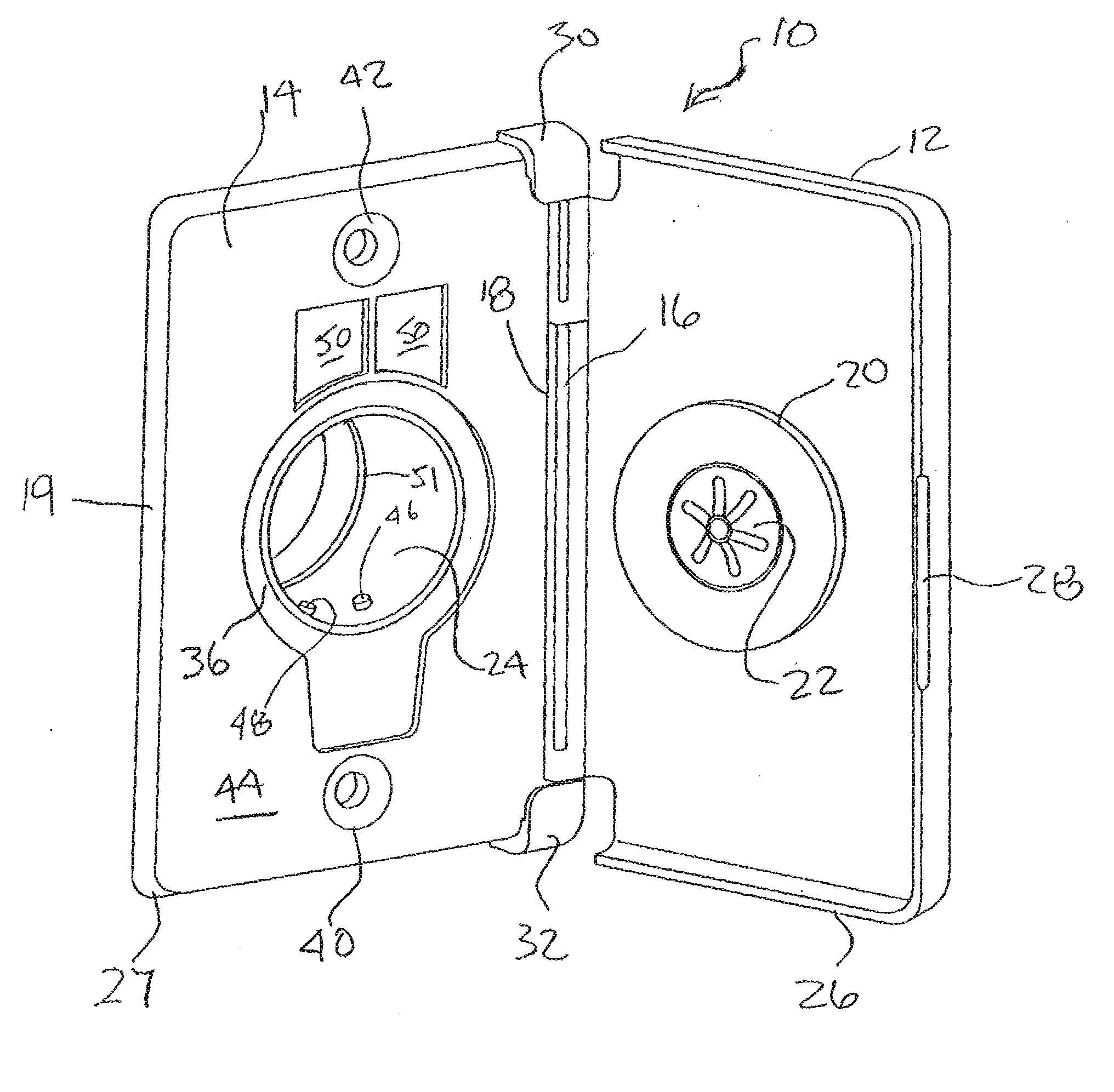
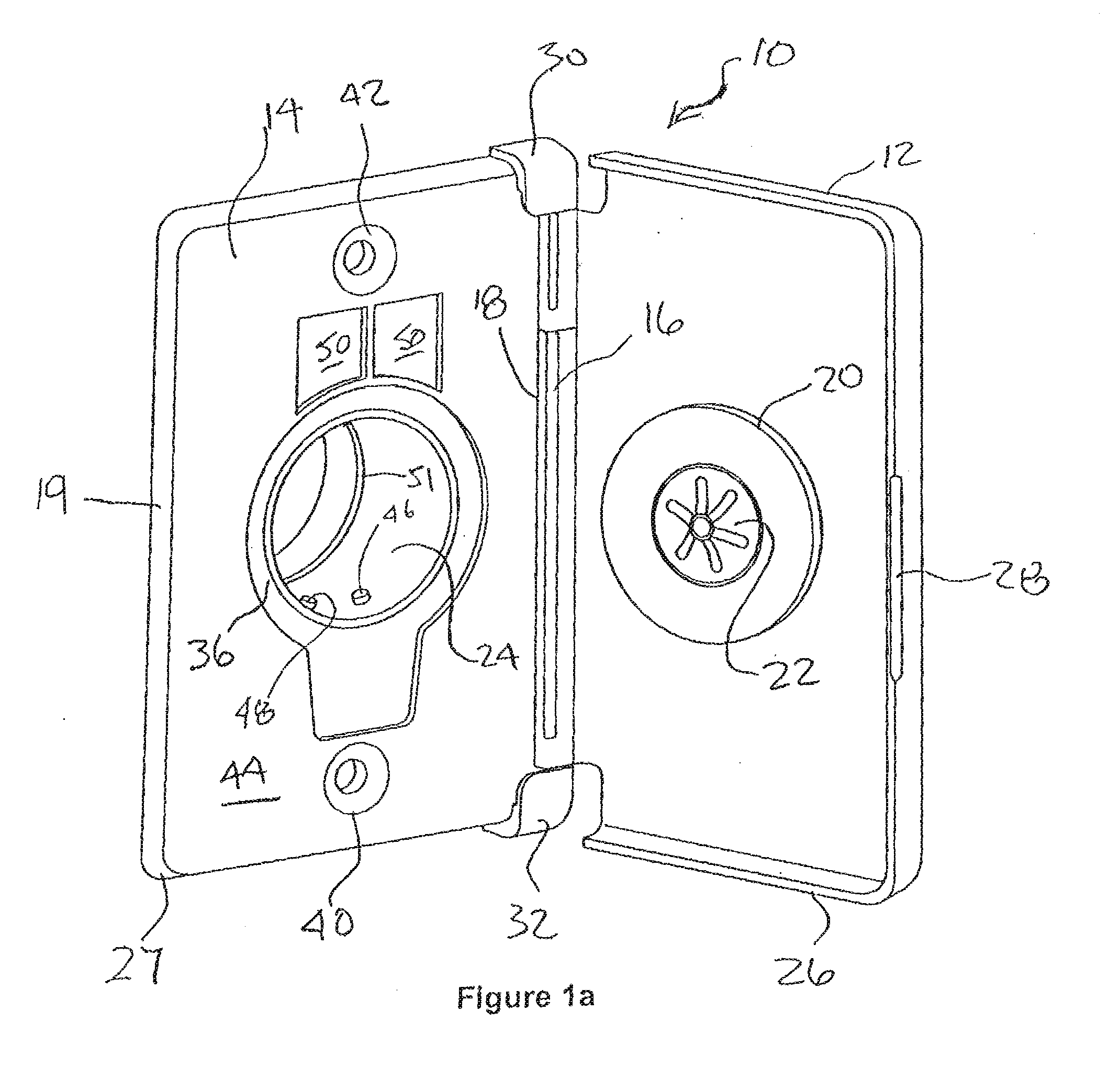
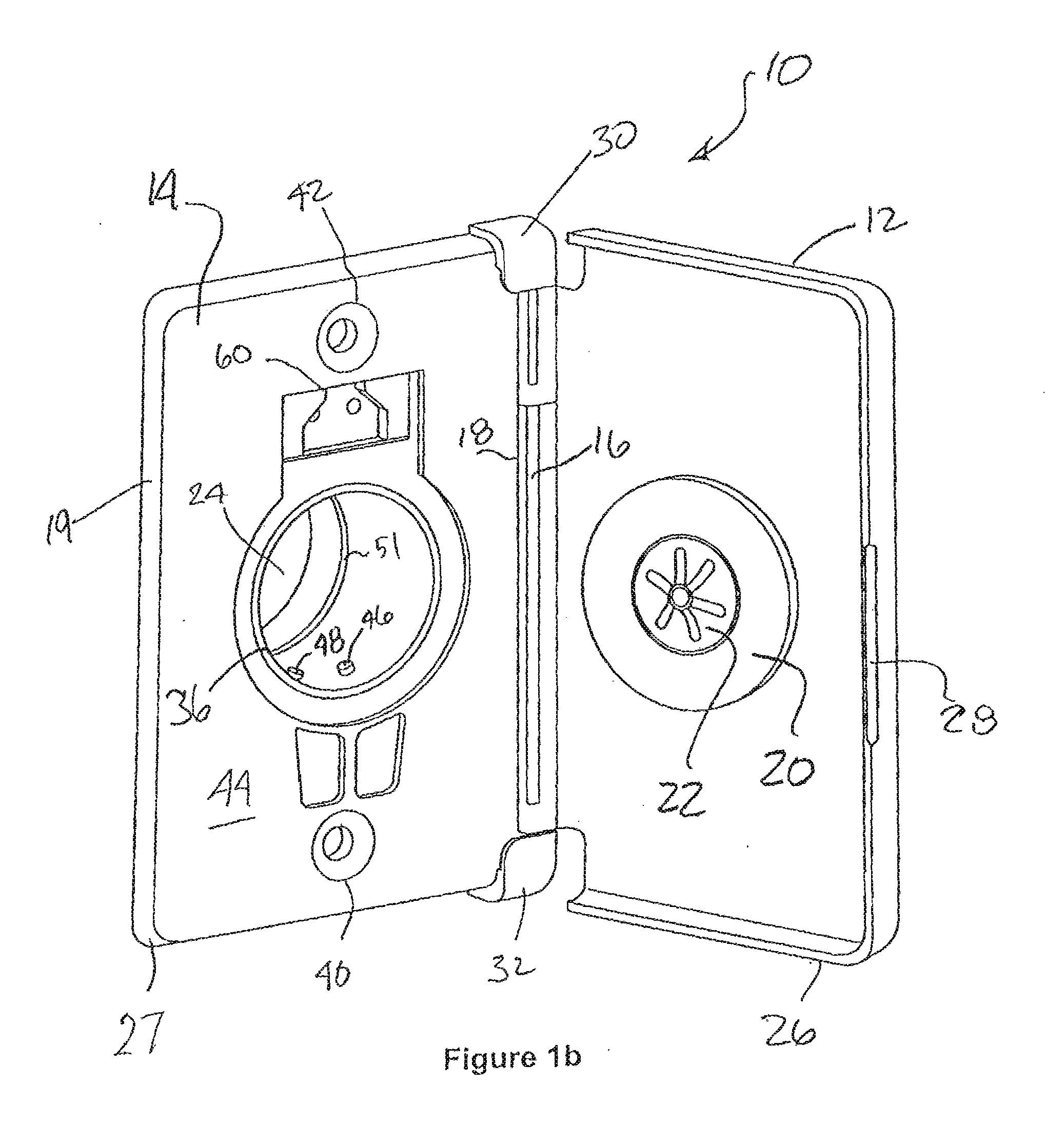
[0025]The present invention is directed to an improved vacuum inlet valve assembly which is comprised of a number of elements, including a cover plate 10 with a hinged door 12, in combination with a sub assembly comprising a valve body 74 with a detachable and reversible attachment or mounting flange 70. The purpose of the vacuum inlet valve assembly is to provide an attachment point to secure a hose cuff 160 from a flexible vacuum hose 180 into a central vacuum system which inlet valve assembly can be used and easily installed in both a new construction or in a retrofit installation. This functionality is achieved by, among other things, the inter-relationship of the elements of the assembly according to the present invention. Each of the elements of the preferred assembly is described in more detail below.

[0026]In FIG. 1a there is shown one embodiment of a cover plate 10 with a hinged door 12 according to the present invention. The hinged door 12 is attached to a face plate 14, by...


PUM


Abstract

A subassembly for use in a vacuum inlet valve assembly for a central vacuum system, the subassembly having a valve body with a wiring compartment and at least one press connection detent means and a reversible mounting flange for connecting to the valve body. The mounting flange includes an attachment portion, a mounting flange wall sized and shaped to cover an open side of wiring compartment and press catch connection elements sized and shaped to interact with the detent to secure the mounting flange to the valve body. Also disclosed is a vacuum inlet valve assembly comprising the above subassembly in combination with a cover plate having a rectangular door, a hinge located on a long side of the rectangular door, and a face plate with a vacuum connection opening. In an alternate embodiment the valve body includes a perimeter wall, attachment openings internal but adjacent to said perimeter wall and a snap fit cover to close an open wall of a wiring compartment.

Description

FIELD OF THE INVENTION[0001]This invention relates to central vacuum cleaning systems, and accessories and components therefor such as inlet valves. More particularly, this invention relates to inlet valve assemblies of the type that permit hand held portable hoses with suction wands to be connected to the central vacuum system. Most particularly this invention relates to inlet valve assemblies of the type that can be adapted to include a current carrying connection for power heads of the type that are mounted at the end of the hand held suction wand.BACKGROUND OF THE INVENTION[0002]A central vacuum system comprises a vacuum motor and dust collecting waste receptacle, located in a remote area of a fixed dwelling, such as a garage or basement. Central vacuum systems may also be installed in mobile homes and recreational vehicles. A series of connected plastic pipes are provided throughout a building, which are connected to a plenum associated with a central vacuum motor. A series of ...

Claims


Application Information

Patent Timeline
IPC IPC(8): F16L5/00
CPCA47L9/246A47L5/38Y10T137/698
Inventor MANTYLA, JAMESBIRD, ANDREWWARD, JOHN
Owner CANPLAS INDS
Features
  • R&D
  • Intellectual Property
  • Life Sciences
  • Materials
  • Tech Scout
  • Unparalleled Data Quality
  • Higher Quality Content
  • 60% Fewer Hallucinations
Learn More